The following instructions apply to the Nettigo Air Monitor in version 0.3.3 STD & PRO. If you have a different version, see the Knowledge Base section for instructions. The general principle of soldering and assembly is common to all our sensors - but keep in mind that they differ in details.
In final assembly we will use all modules built in previous steps:
- Mainboard
- HECA module
- Depending on version:
¶ NAM sensor - assembly instruction
Main difference between STD and PRO versions is extrenal antenna in PRO version. If You have proceed according to our instructions earlier, at this stage there is no difference between STD and PRO kit assembly. Of course, PRO has it's external antenna, pictures in this tutorial are done with STD version.
¶ Environment sensor
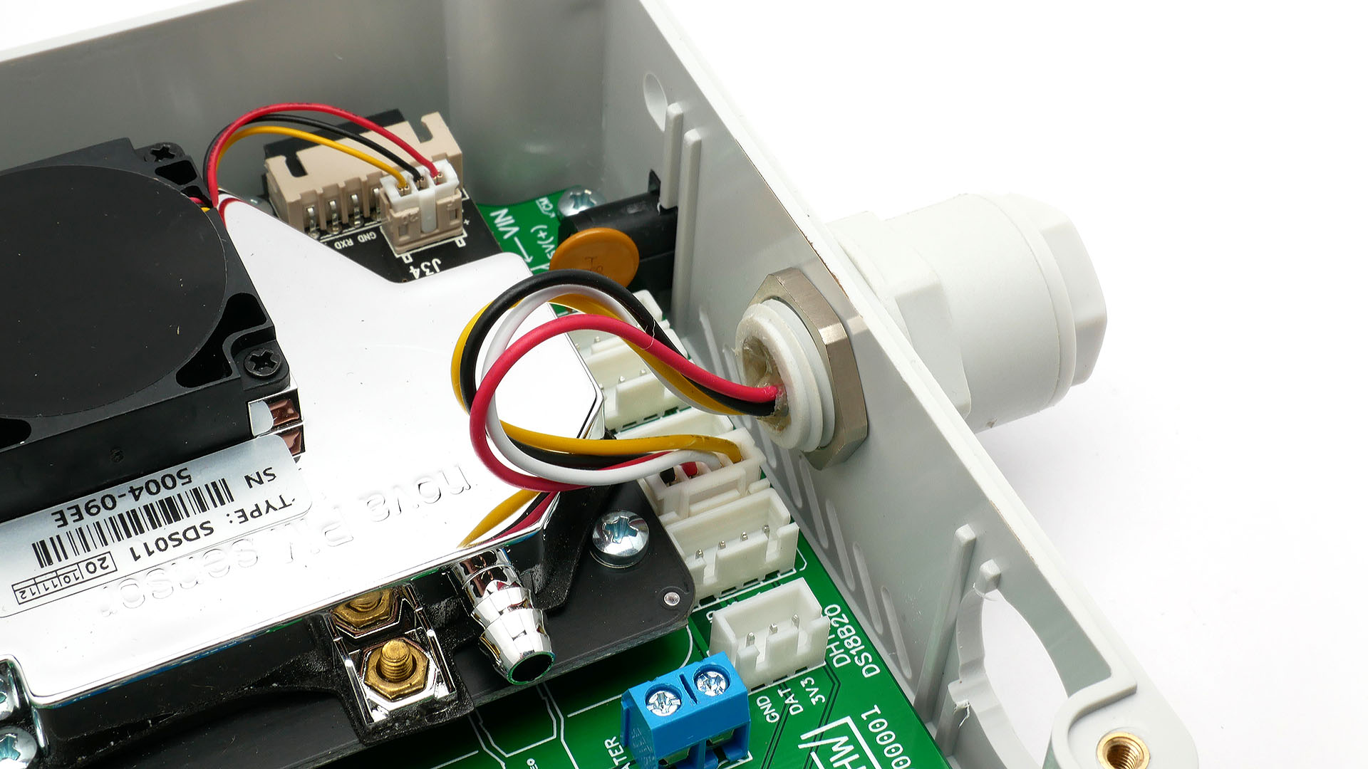
With metal M6 nut screw barrel case for environmental sensor. Connect plug into middle socket of I2C 3V3 connectors.
If You have kit with SHT31/BMP180, soldered according to our guide there is no difference between BME and SHT versions.
¶ Presoldered kits
With presoldered kits with SHT/BMP sensor there is one difference. SHT31 and BMP180 are soldered on two separate cables & connectors (not in sandwich mode on single cable like in our guide). In that case - place SHT31 inside environemental case and BMP180 connect to third I2C 3V3 socket. BMP180 is protected with heatshring tube and is meant to be place inside NAM main case. Shrink tube protects before accidental shortcuts. BMP180 measures pressure, which is leveled inside case with atmospheric.
Remeber to block airflow between NAM case and environmental sensor (You can use hot glue). This is explained in BME280 soldering instruction, but this applies both to BME280 and SHT31 versions.
¶ HECA sensor
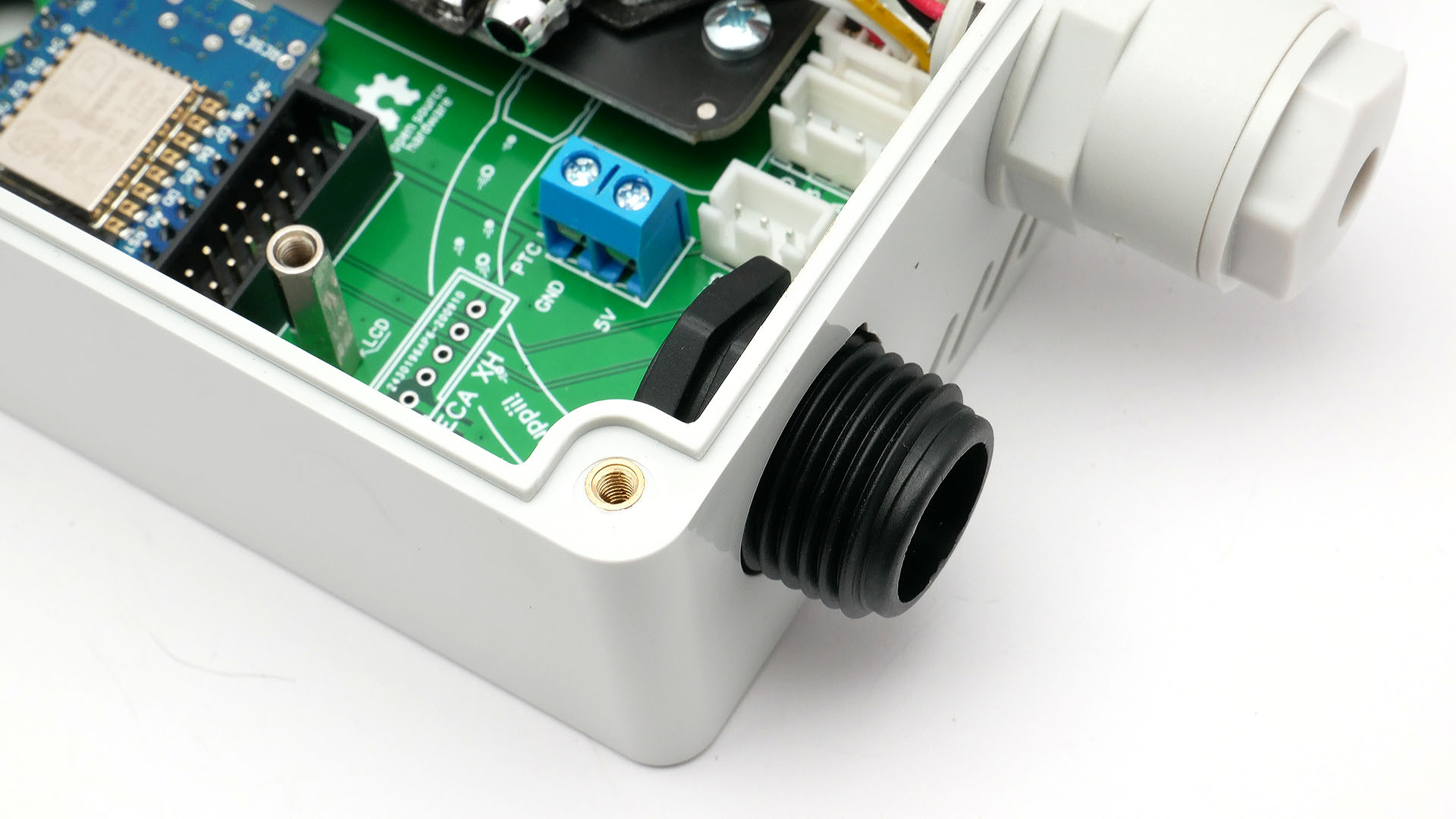
Short, black threaded element put through hole from inside of case.
NOTICE Most of our kits have this element with joint PP stub broken off. If Your kit comes with not prepared one following this instructions.
In other case proceed further.
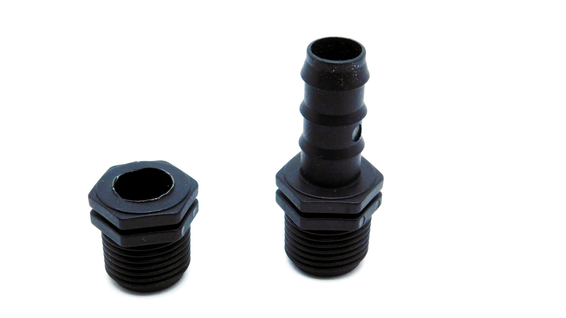
Most kits have this element as seen on the left. If Your kit comes with one like on the right - screw in this element inside the muff.
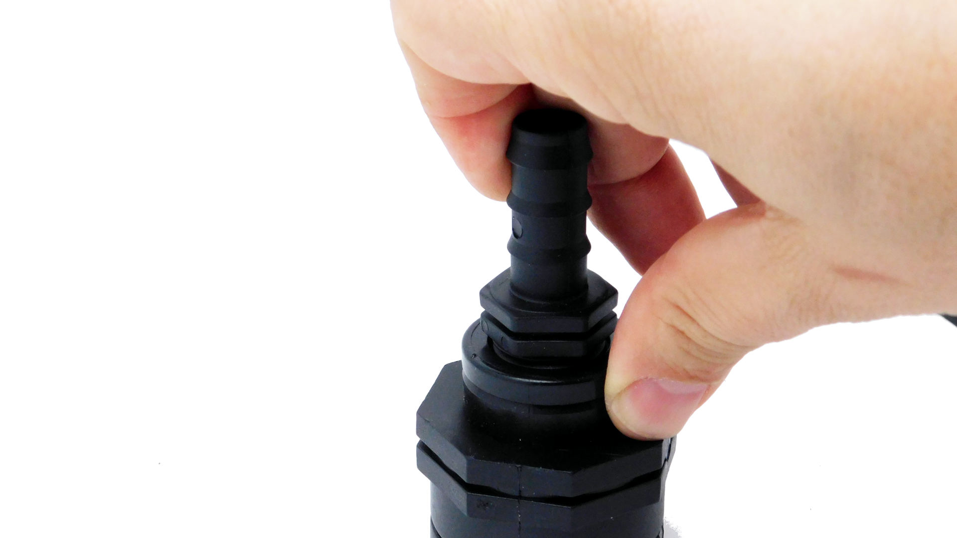
Then put pressure on the stub, using Your fingers with thumb placed on the muff. Grip the muff with other hand. You can use some cloth and wrap stub to make it easier break stub.
¶ Screw in the muff
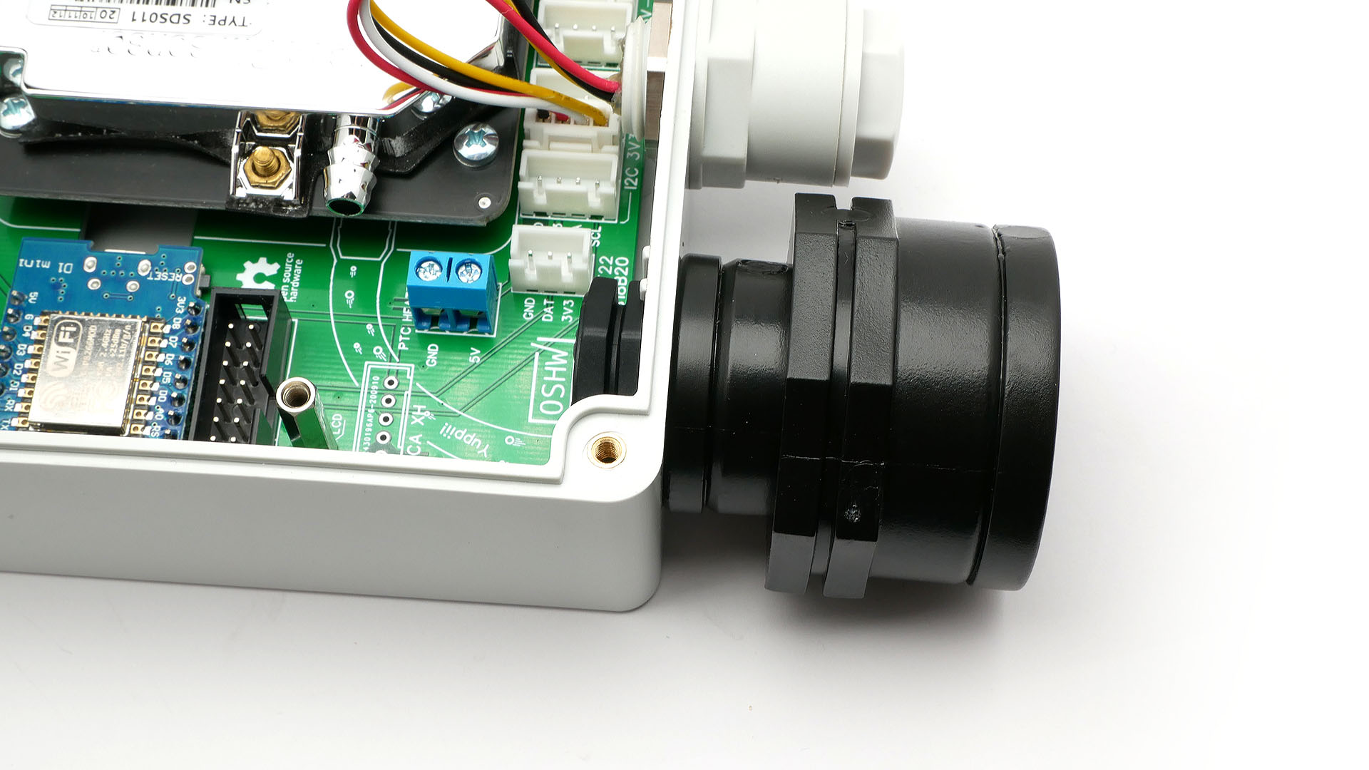
Reduction joint screw onto it from outside. Tighten well. First, the screw joint won't align with NAM case, but after You tighten well muff, it will snap into place.
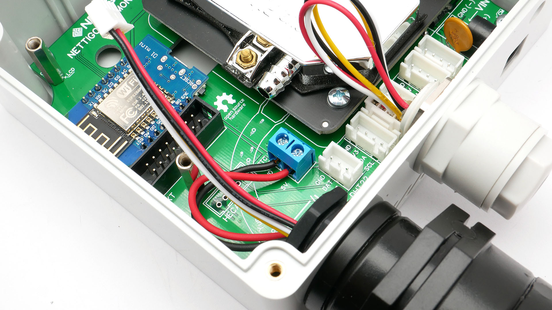
Through joint put cables from HECA module. Power cables screw into blue terminal.
Double check if You have connected them in correct order. Reversing them may damage sensor.
Red cable to terminal described 5V and black one to GND. Double check that you have not mistaken the order.
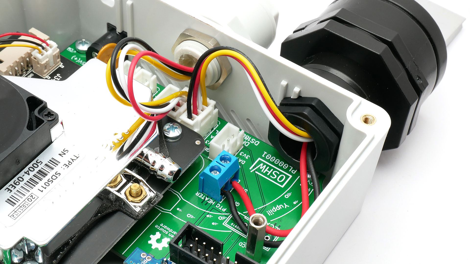
White connector put into left socket I2C 3V3
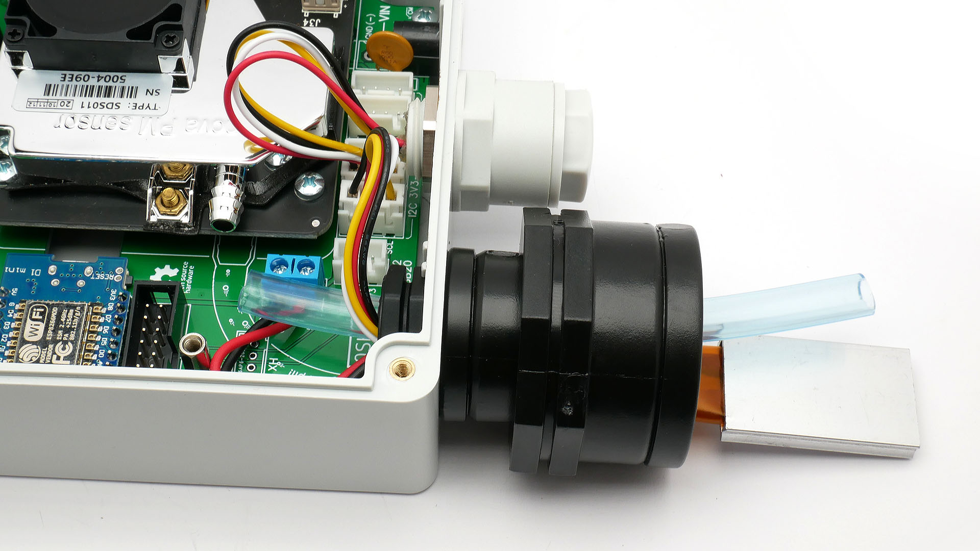
Clear technical hose place inside of hole in HECA module and pass it inside.
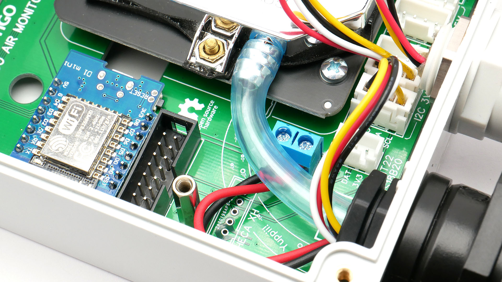
Now, place hose onto SDS011 air inlet. Make sure hose does not bend sharply. That may limit air flow, resulting in wrong PM readings.
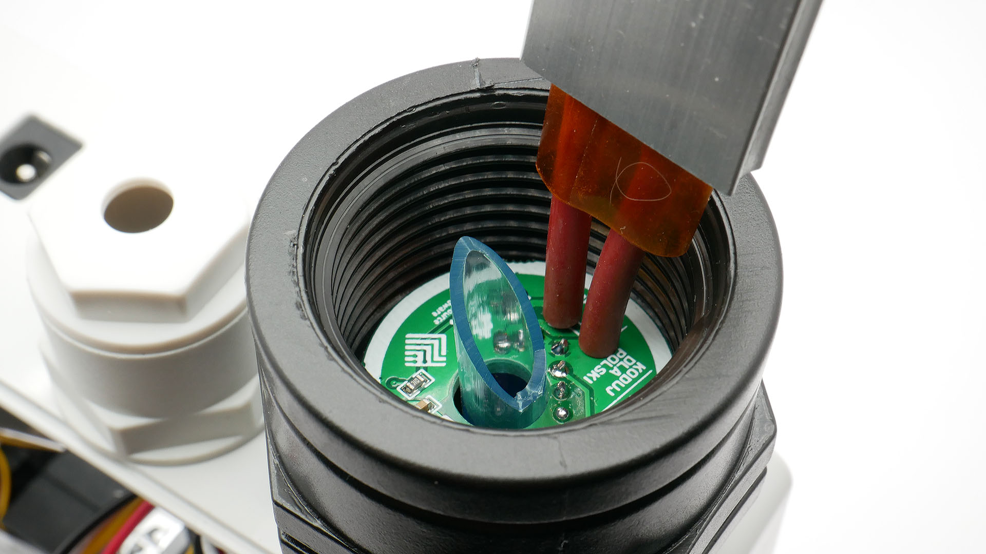
Excess of hose should be cut off. Try to cut it under 45° degree - water condensate will not block the air supply.
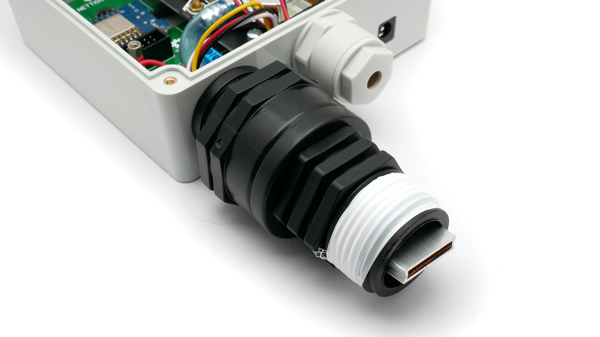
Screw joint into reduction.
On lower therad we recommend to use PTFE tape for additional sealing. If sensor will be exposed on direct rainfall, water will gather on second reduction top edge. Without tape it may get inside and damage make PTC element not working correctly.
If You don't have PTFE tape, You can screw case and then put duct tape around lower reduction top edge to make raindrops run off. Not a perfect solution but better than nothing.
For sensors protected by some roof (not exposed on direc rainfall) additional sealing is not required.
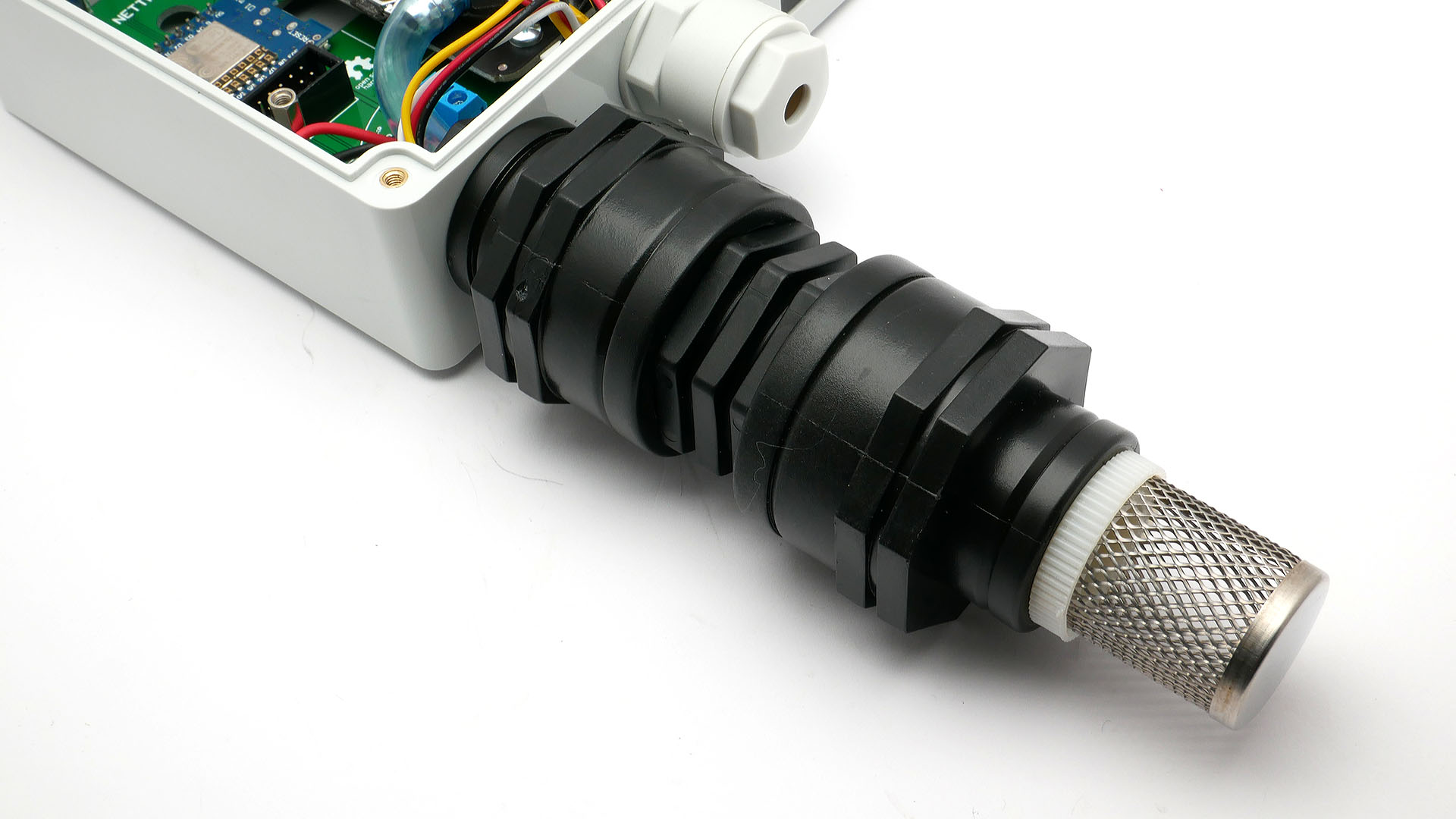
Screw second reduction and suction basket (works as protection before insects).
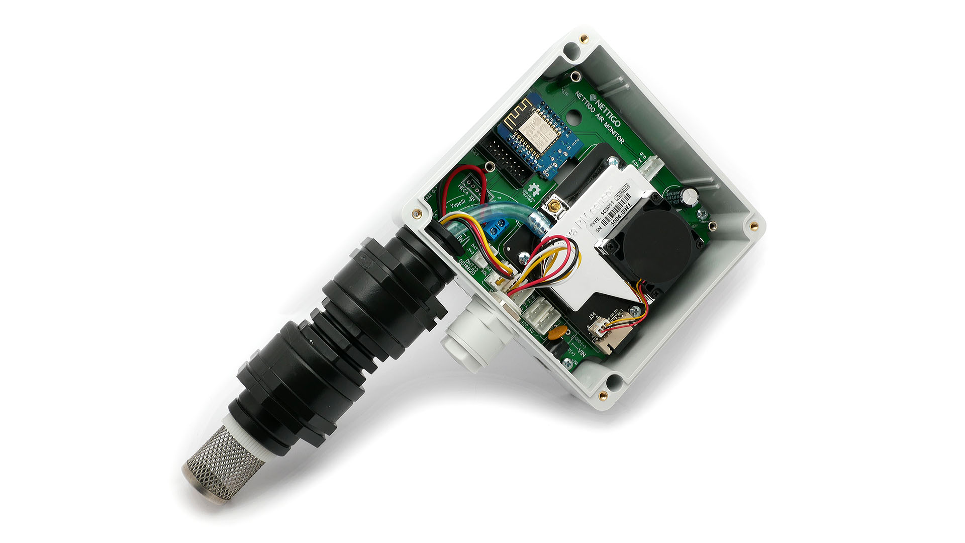
Sensor is almost ready!
¶ Final test
Before You place case cover, do test if everyhing works.
Conncet power and configure firmware (if not done that before). Check if all modules report data.
¶ Placing a cover
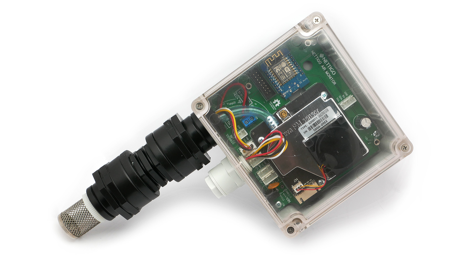
Before screwing cover use thin, white silicone sealing and place it in groove on cover. Sealing is a bit longer than groove lengths so when You make whole loop cut execess off. We suggest starting placing sealing in near one of bottom screws.