The following instructions apply to the Nettigo Air Monitor in version 0.3.3 STD. If you have a different version, see the Knowledge Base section for instructions. The general principle of soldering and assembly is common to all our sensors - but keep in mind that they differ in details.
¶ Before you start soldering
Read our guide on how to solder our kits.
If you are soldering a kit from Nettigo then you can basically skip this step. We send the Wemos D1 mini board with pre-programmed firmware. We use the latest stable version of Nettigo Air Monitor Firmware.
If you are gathering the components yourself, before soldering, it is good to check if the Wemos D1 mini board works ok, can be programmed and if the firmware is working properly on it. Information on how to upload the firmware can be found in Knowledge Base.
After installation, the first run will take from several to several dozen seconds. After completing it, you should see a WiFi network named with SSID: "NAM-XXXXXX", where the sensor identification number is located instead of X. Write down this ID - it will be useful later. Connect to this network, enter http://192.168.4.1 in your browser and check if you can see the green configuration panel. You can also configure the Internet connection settings by entering the WiFi SSID and password.
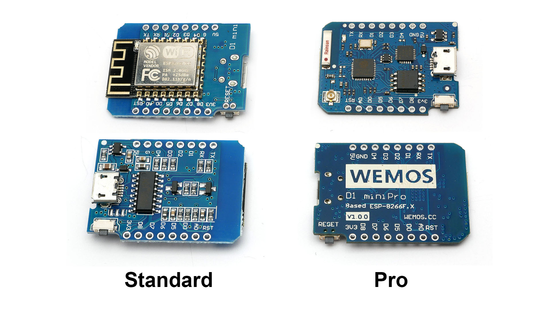
If you do not know which version of Wemos D1 mini you have, take a look at the photo below.
¶ NAM 0.3.3 STD motherboard soldering process
¶ Wemos soldering
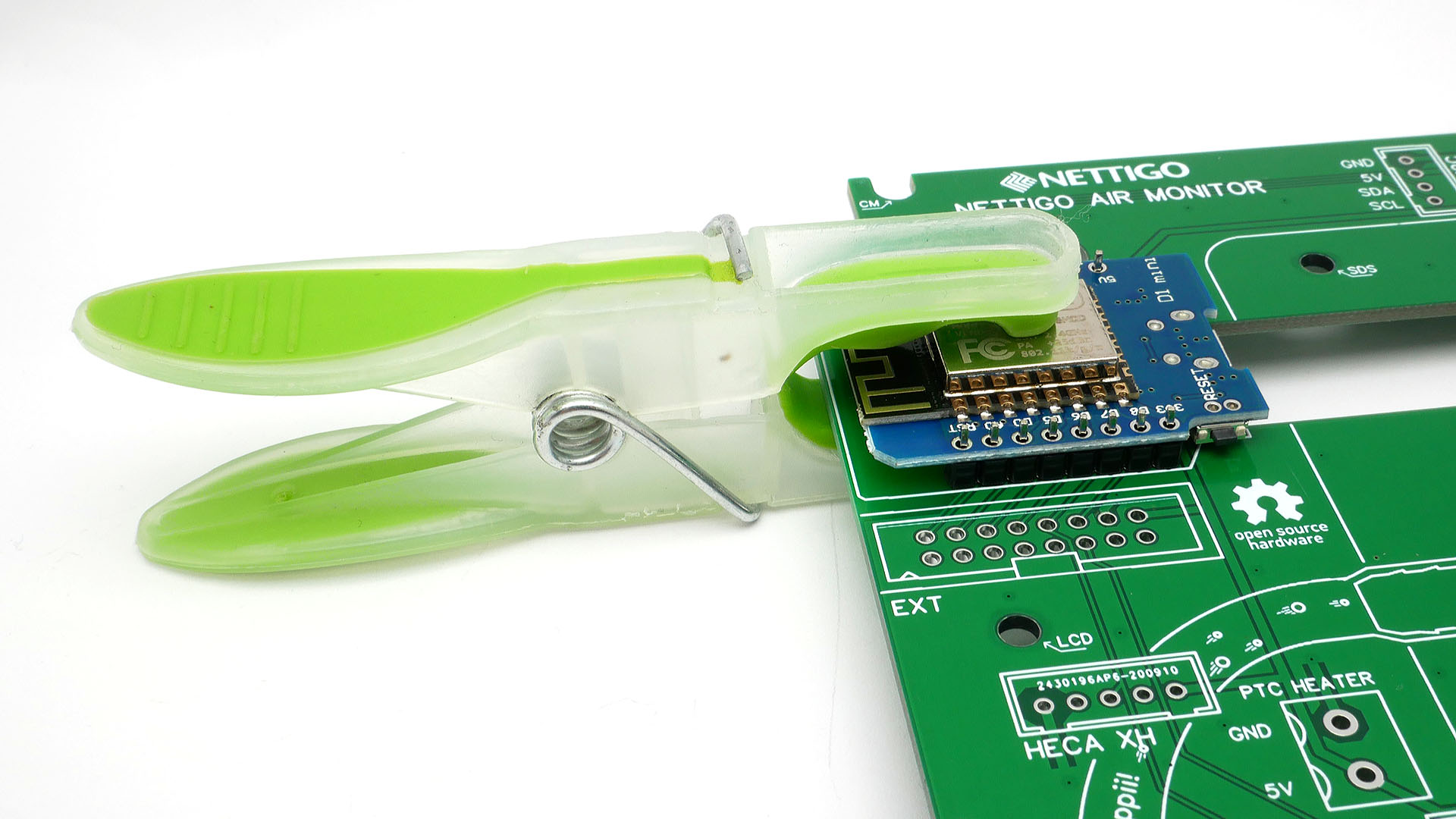
This is original way of soldering Wemos. We recommend soldering with sockets (see below)
Insert two 1x8 pin headers into the PCB, then place Wemos D1 mini board on them. Remember that the micro USB port should face the center of the motherboard and the antenna should on PCB's edge. For ease of use, fasten board with a clothes peg. Now you can easily solder Wemos D1 mini on both sides. When soldering the GND pad (signed G), hold the soldering tip a little longer until the tin covers its entire surface. GND pads are usually connected to large copper areas. Their heat capacity is therefore greater.
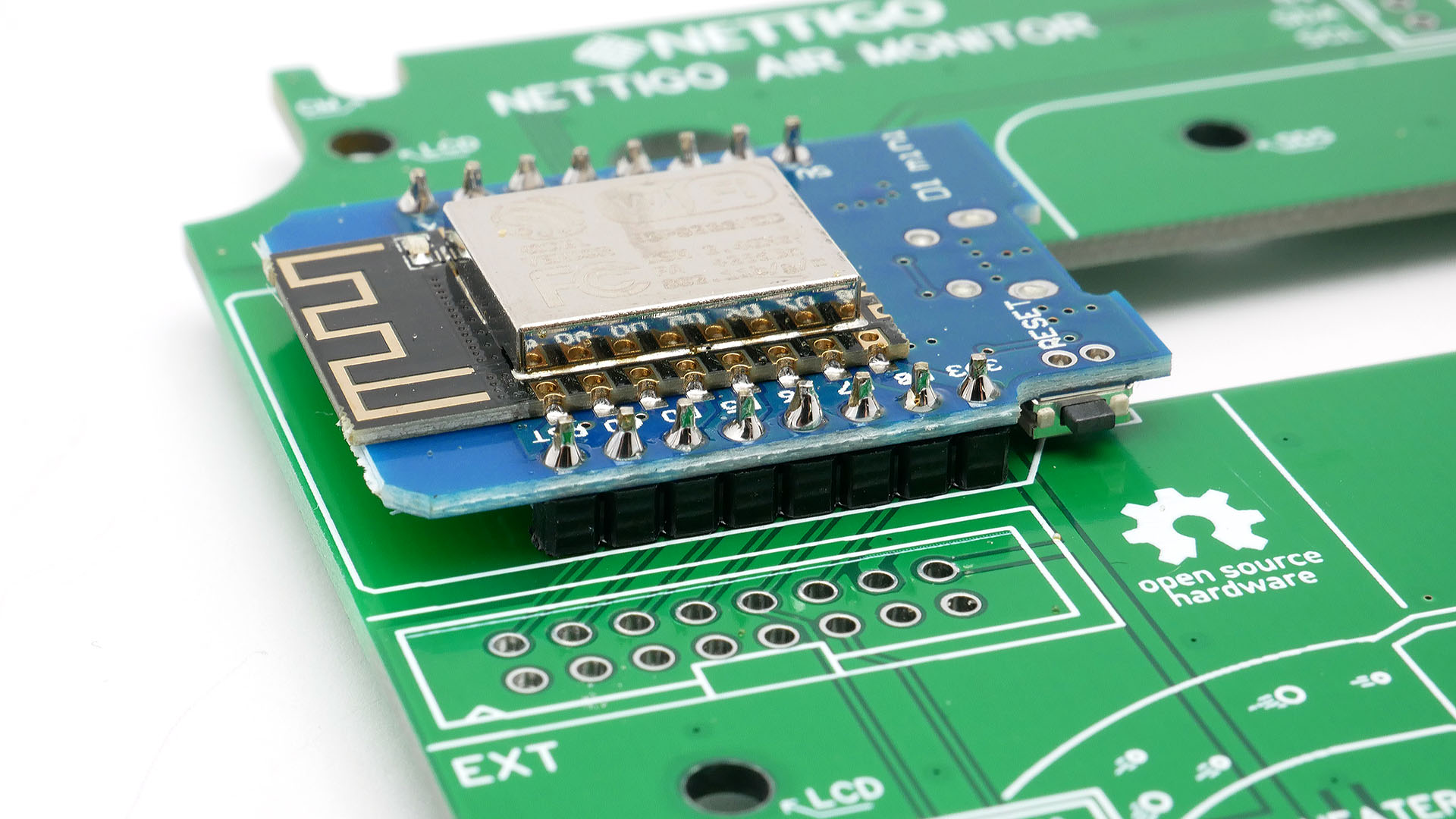
The joints made in correct way should be shiny. If yours are mat you should consider using flux (eg. rosin) and reheat the connection with the soldering iron. The shape of joint should be slightly conical. If you somehow ended with a large tin ball, the joint needs to be soldered once again.
Recommended way of soldering
Soldering sockets and then placing Wemos there has an advantage over classic method - in case of Wemos failure it is easy to replace it. If You solder it directly to PCB, then replacement can be hard.
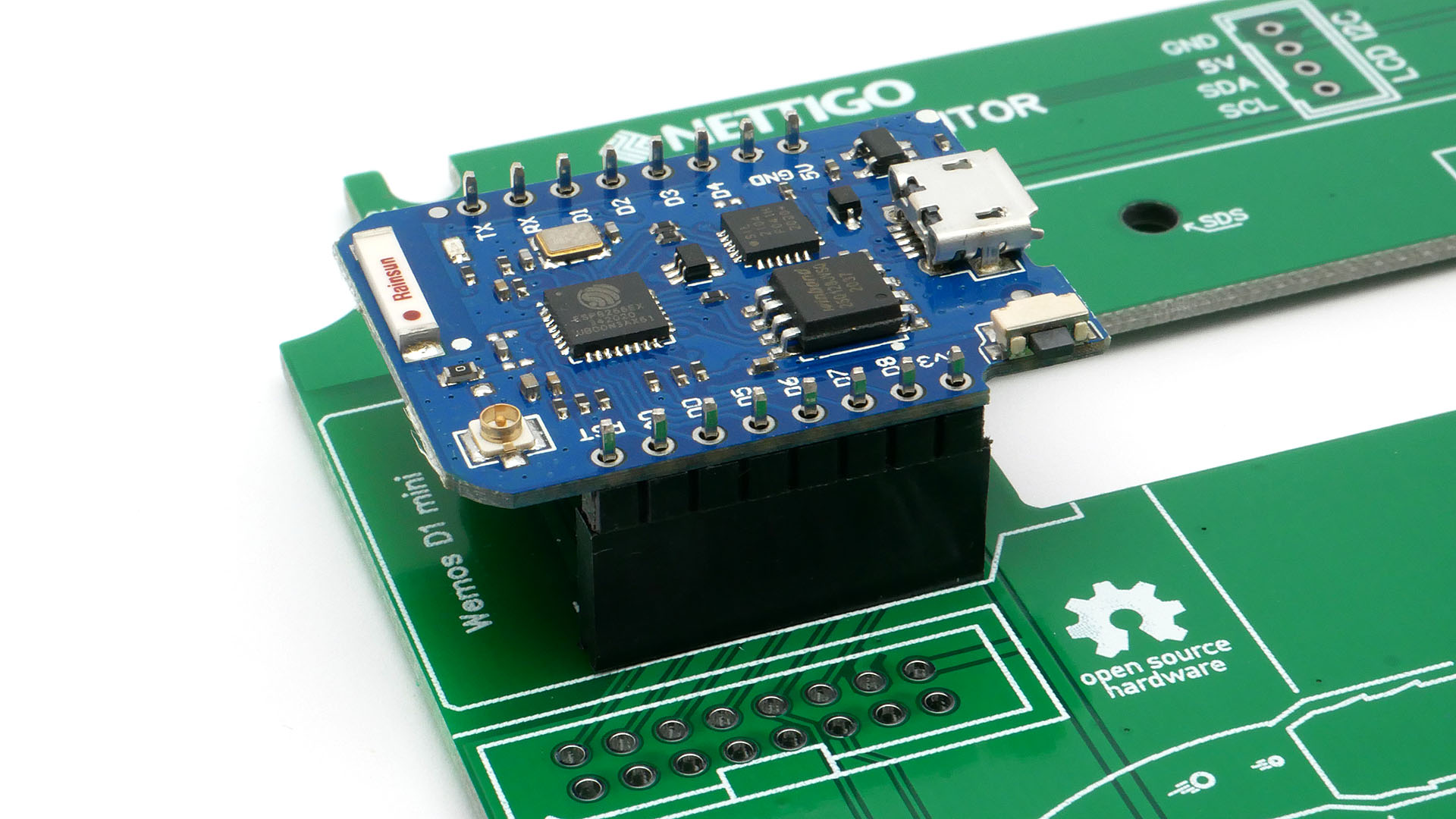
First solder sockets (8 pins) which should be included with Wemos.
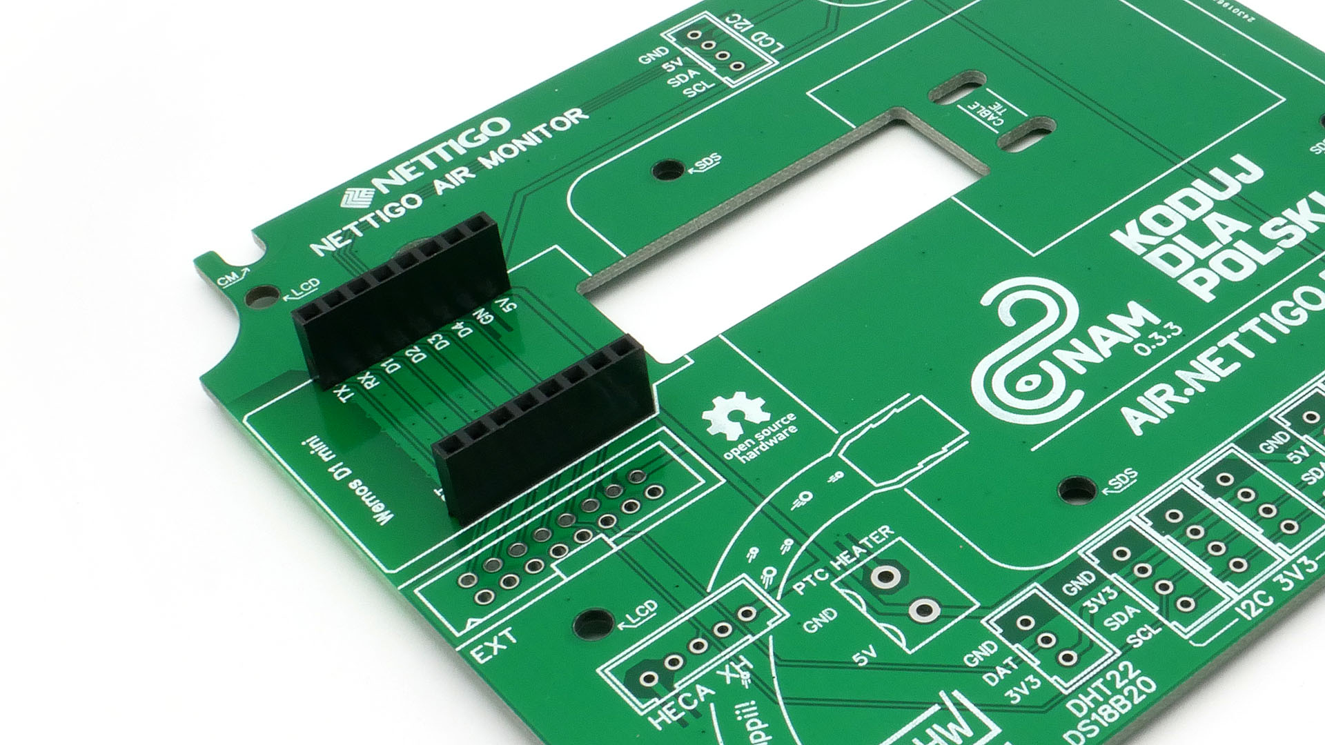
Next place goldpins (1x8) into sockets and put Wemos onto it. On pictures there is Wemos PRO, but for STD is exactly the same procedure. Next solder goldpins.
¶ I2C connectors
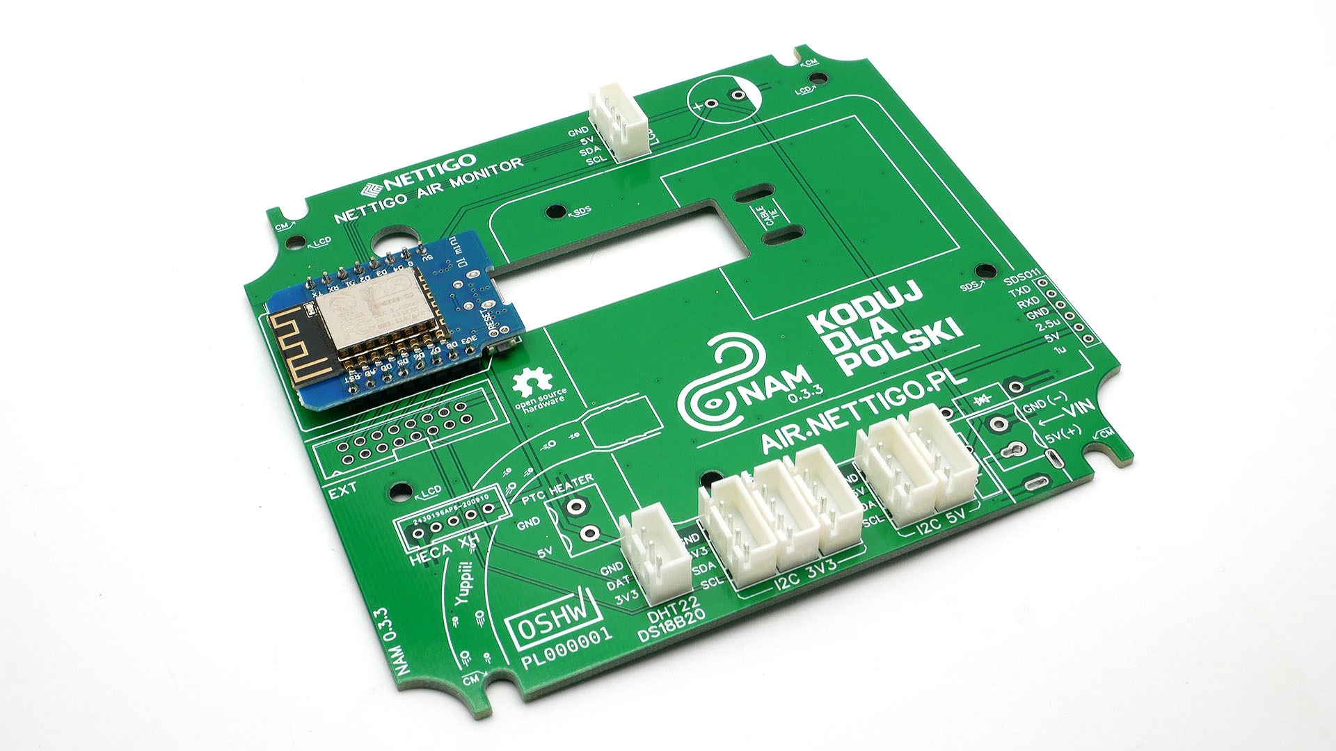
Take a good look at how the DHT, I2C 3V3, I2C 5V and LCD I2C sockets are oriented. Then hold them with your fingers and turn the PCB over. To make things easier, you can solder one pin from each socket and check if they are straight. Then solder the remaining pins. Check all joints carefully. Now check again It's easy to miss something in the maze of solder joints. It also happens to us. The soldered sockets should look like in the picture above.
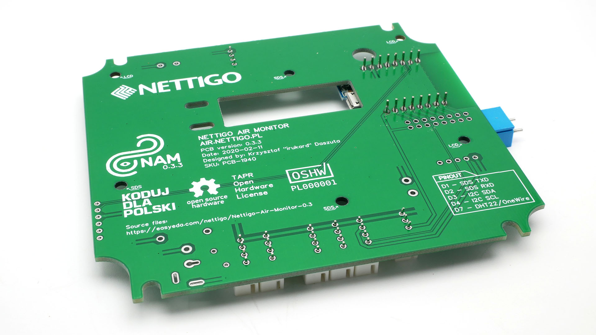
This blue connector (under PCB on the right) will keep the board leveled while we solder the white XH2.54 sockets.
¶ Other connectors
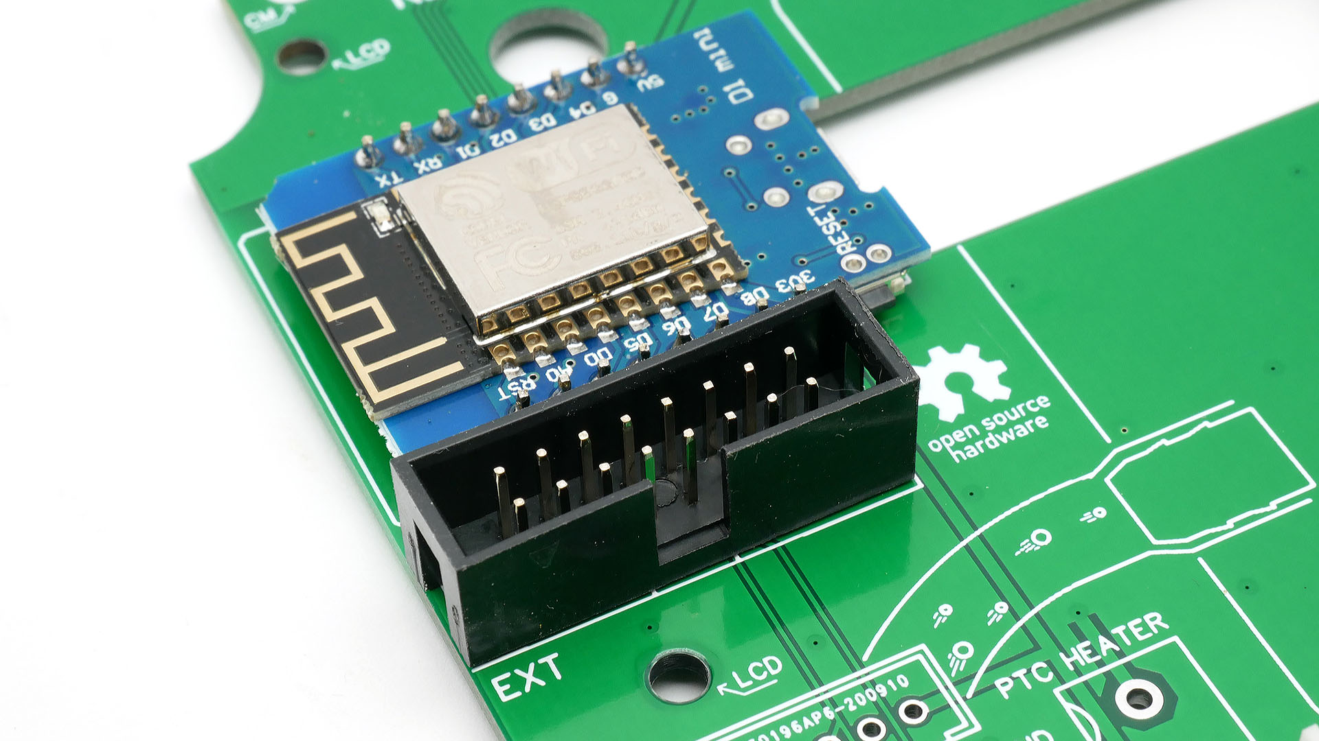
Below the Wemos board, solder the black IDC16 extension connector labeled EXT. This connector allows you to use all 16 pins of the Wemos board. This is our favorite connector, because we can diagnose NAM without removing the board from the enclosure. It allows for Wemos reflashing and connecting additional experimental extensions.
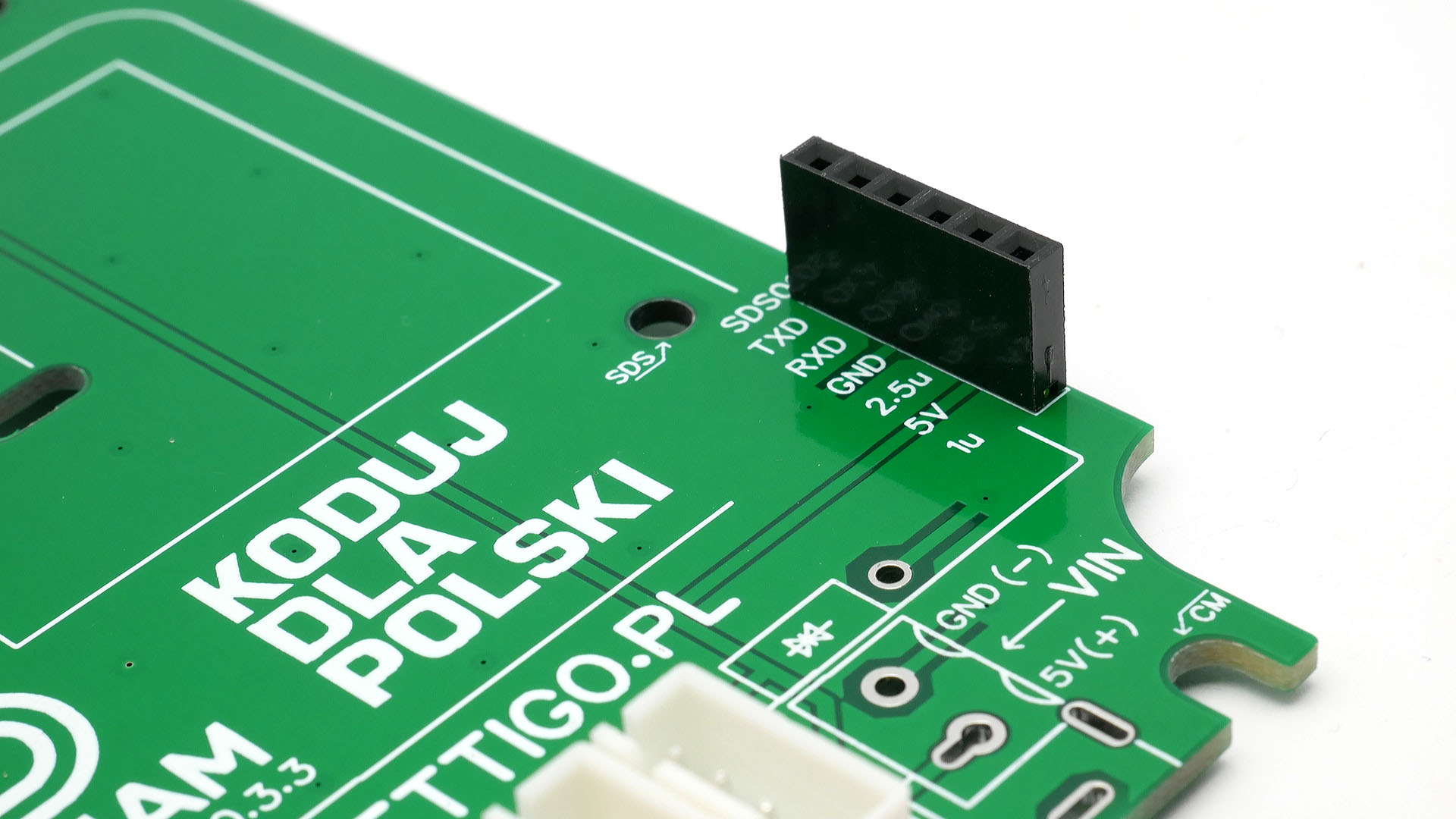
At the right edge of the board, solder the 1x6 SDS011 connector (the short one).
¶ Power related elements
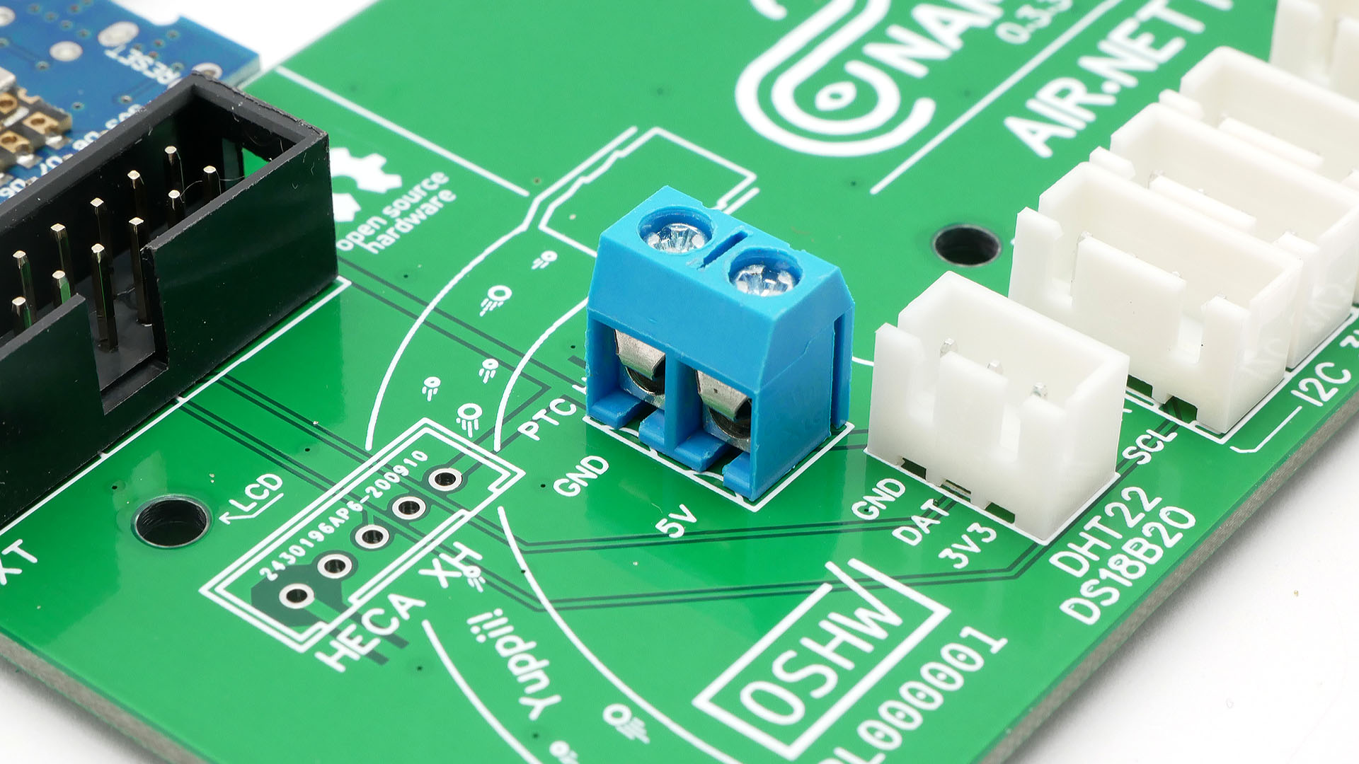
Now is a good time to solder the blue screw terminal. It will power HECA heating element. There is a huge piece of metal inside this screw terminal. You will need to hold the tip of soldering iron a little longer.
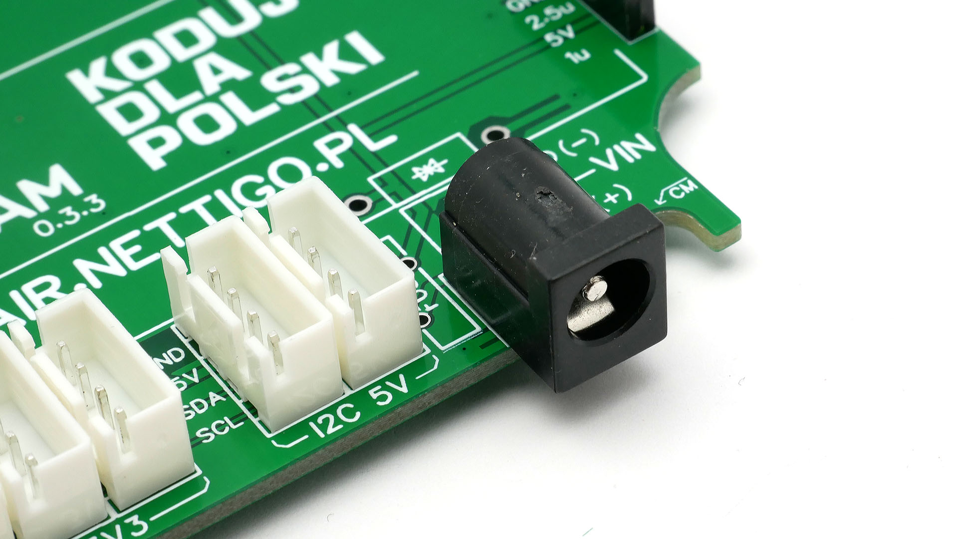
NAM 0.3.3 allows you to supply power in two ways. The first is the black connector soldered to the motherboard. It is a convenient and quick method to install. The second way is powering through the screw terminal. Useful when you got source of higher voltage and you need to use a Step-Down converter. In most cases, the black connector should be soldered.
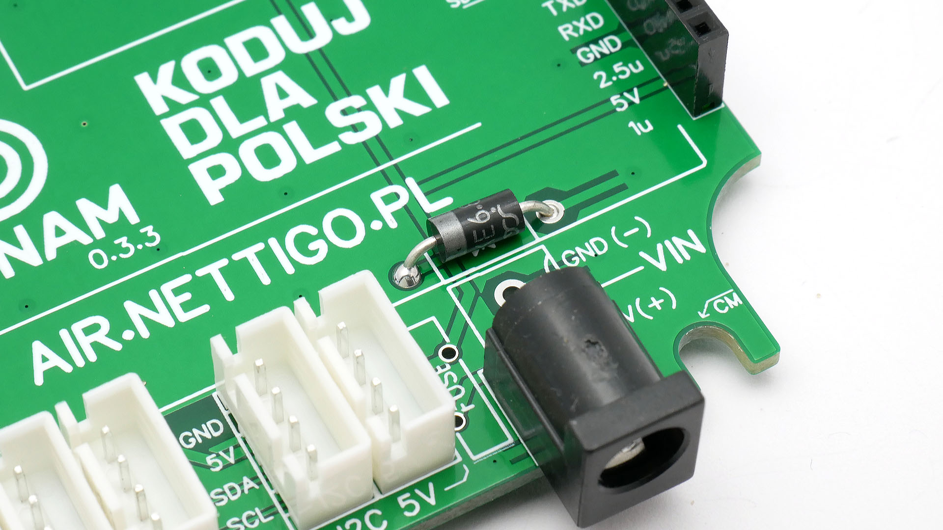
Time to solder an optional safety element - the TVS (Transient Voltage Suppressor) diode. This is an element that should short circuit in two situations: when a voltage above 7V is supplied or when the power supply is connected the other way round. The diode responds instantly. Pay attention to the polarity of the diode. The light strip should point to the left as shown in the photo.
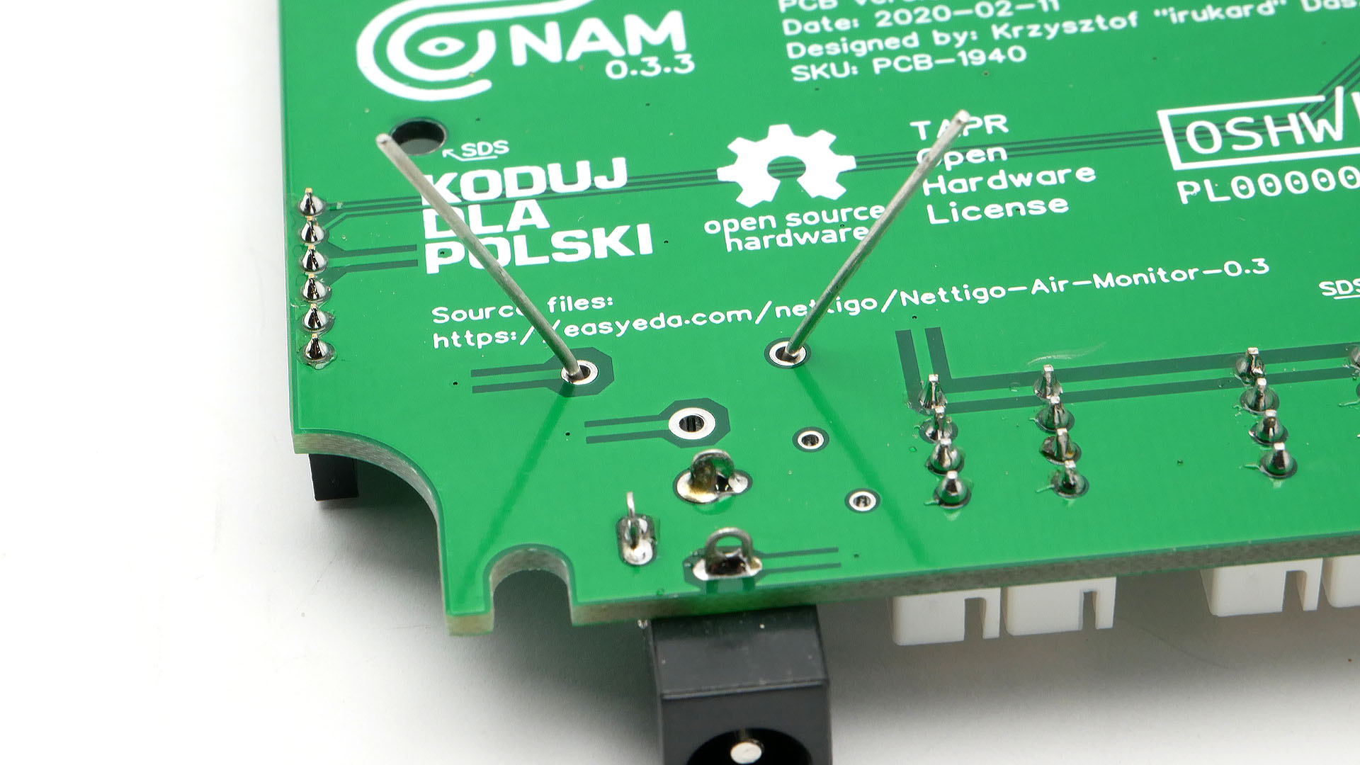
Standard practice during soldering trough hole components is to bend the legs of element so it does not fall off from PCB. After soldering, cut the legs with pliers. The same advice will also apply to the next elements.
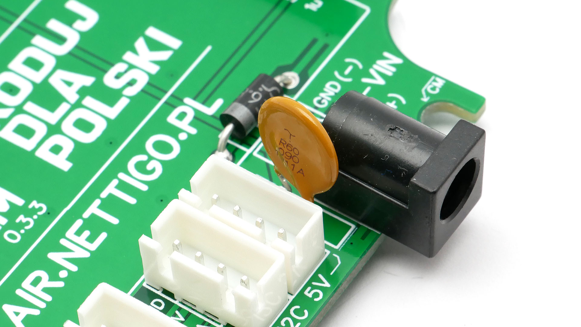
Solder the polymer fuse. It's that orange element. And make sure it stands straight and does not touch anything. In short circuit situation (for example made by TVS), this component must heat up and break the circuit.
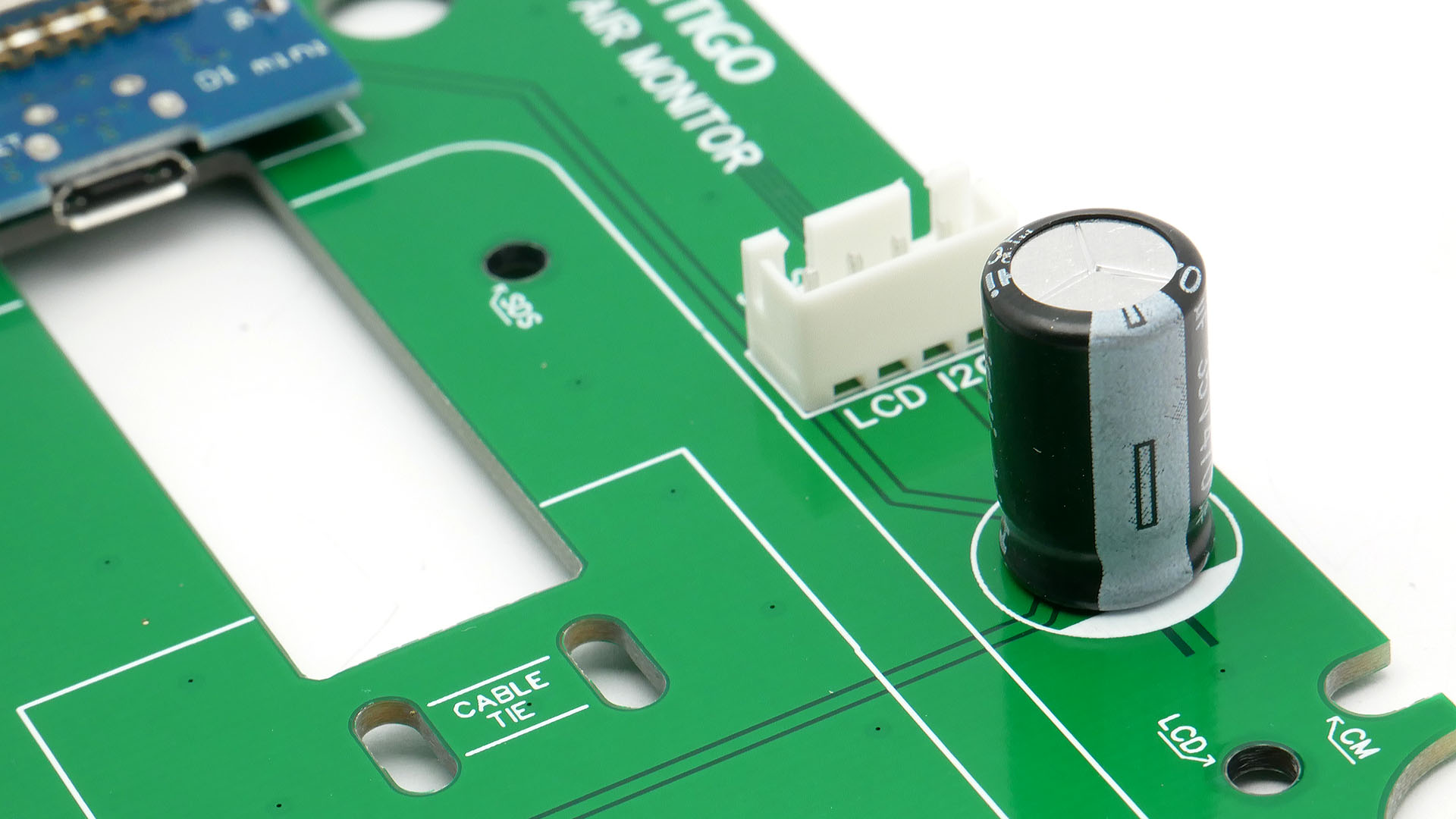
Solder the capacitor. The method is the same as for diode and fuse. Note the polarity. The minus on the capacitor must be on the same side as the white mark on the PCB.
Now check the polarity of the capacitor for a second time. This is important. A capacitor is not a cure for all the world's problems, but it solves some issues with poor power supplies.
¶ SDS011 mounting
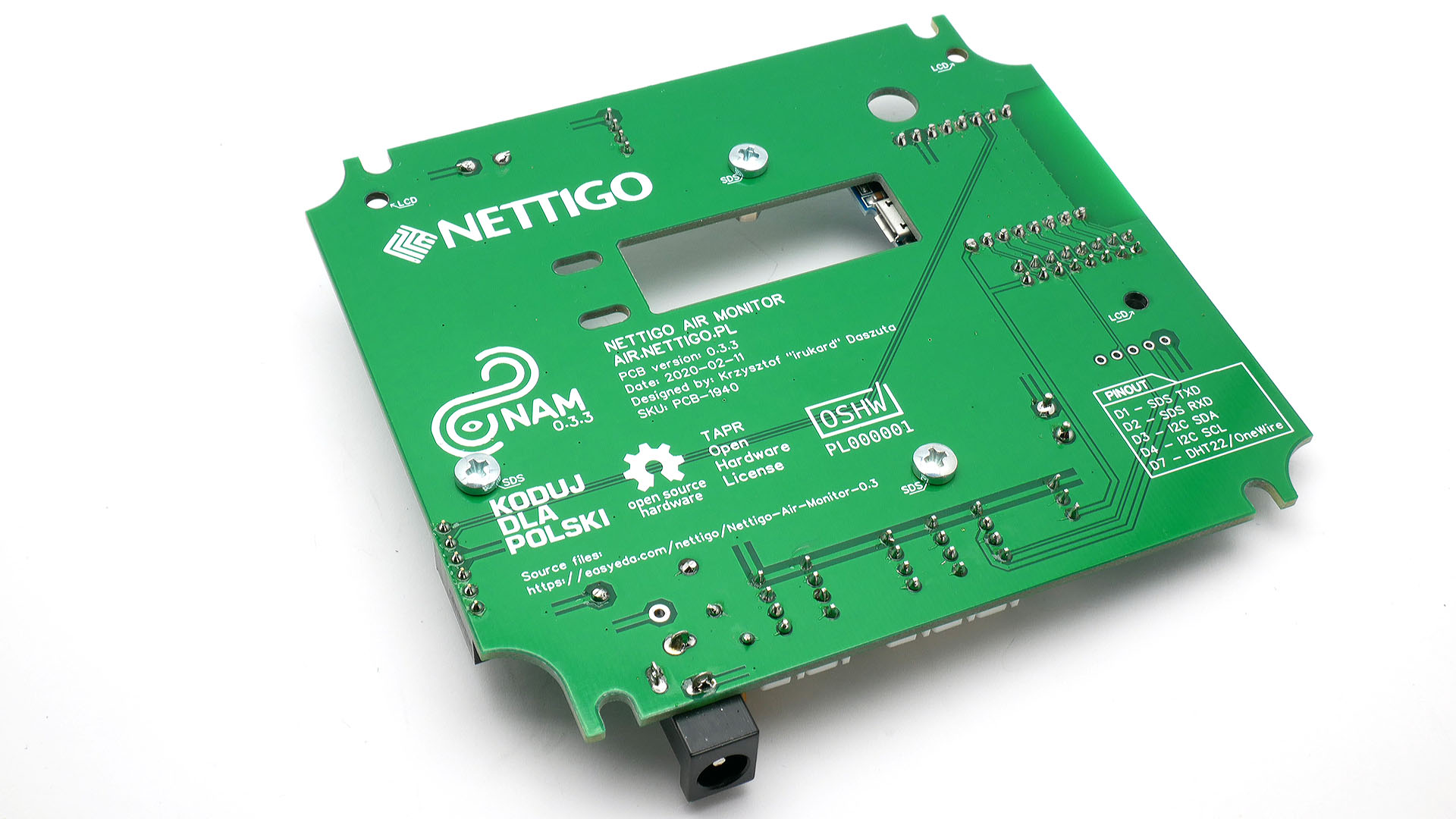
Using three M3x5mm screws fasten three 8mm standoffs to the PCB. The screws should be on the bottom side and should be placed in the holes described as SDS.
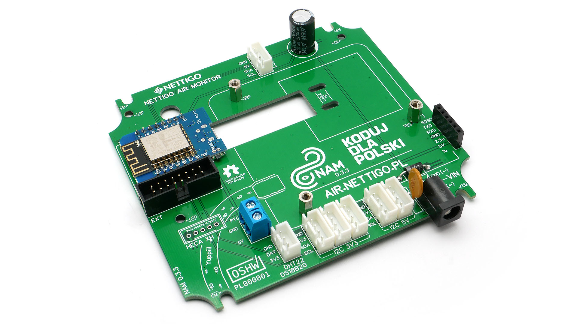
The standoffs should be facing up. Remember to tighten them well.
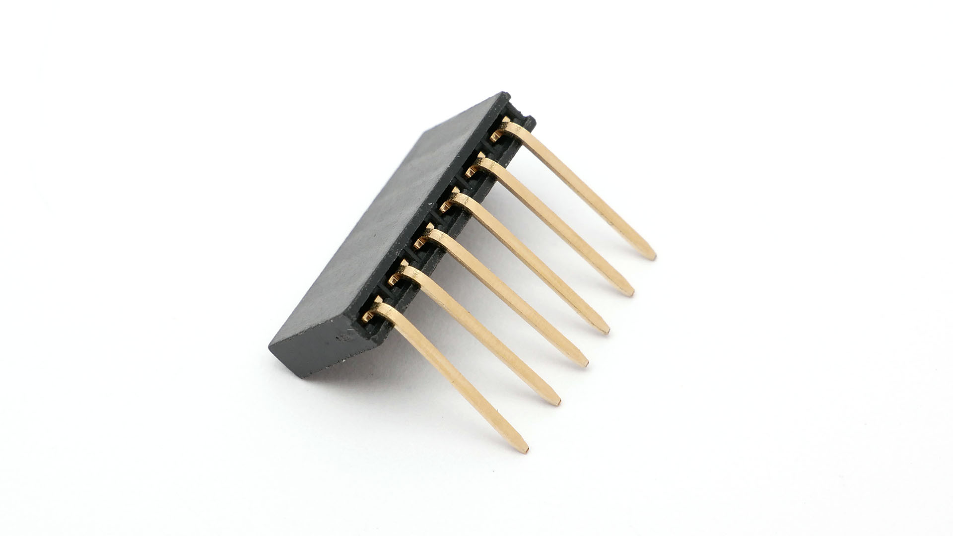
The 1x6 long header should be bent at an angle of 90 degrees. This can be done by bending the pins against the table top.
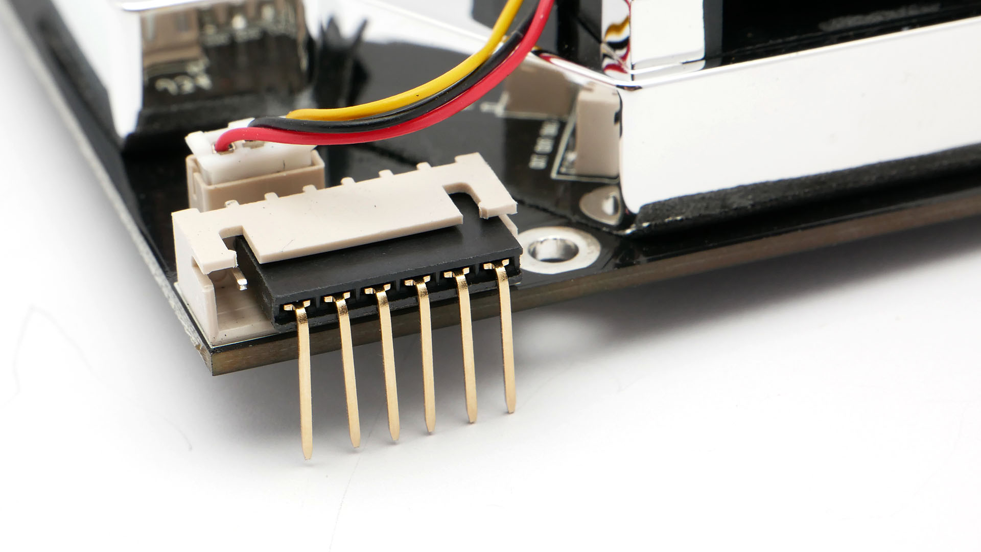
Mount the bent header in the SDS011 sensor. Note that one pin must be left alone (NC means Not Connected).
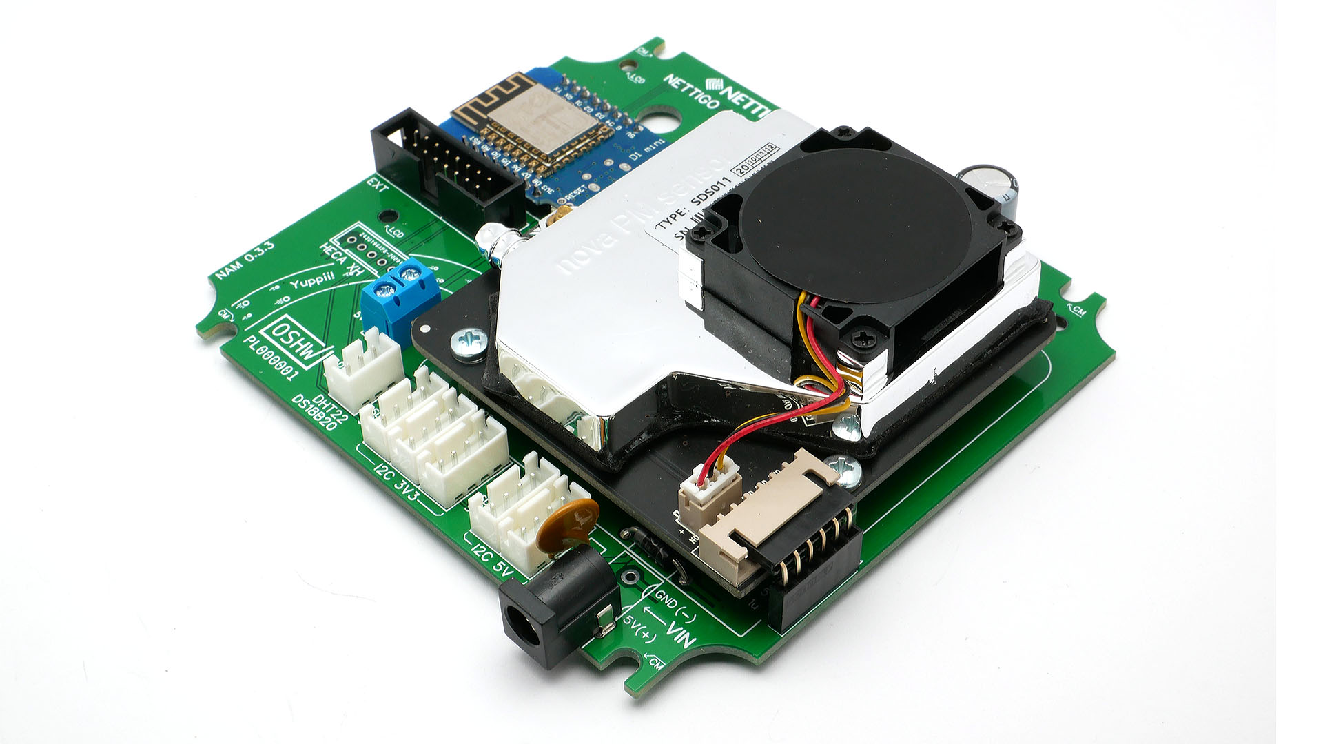
Mount the SDS011 in place. Make sure that all the pins have entered the socket on the board. Using M3x5mm screws, screw SDS011 to the standoffs.
¶ Final elements
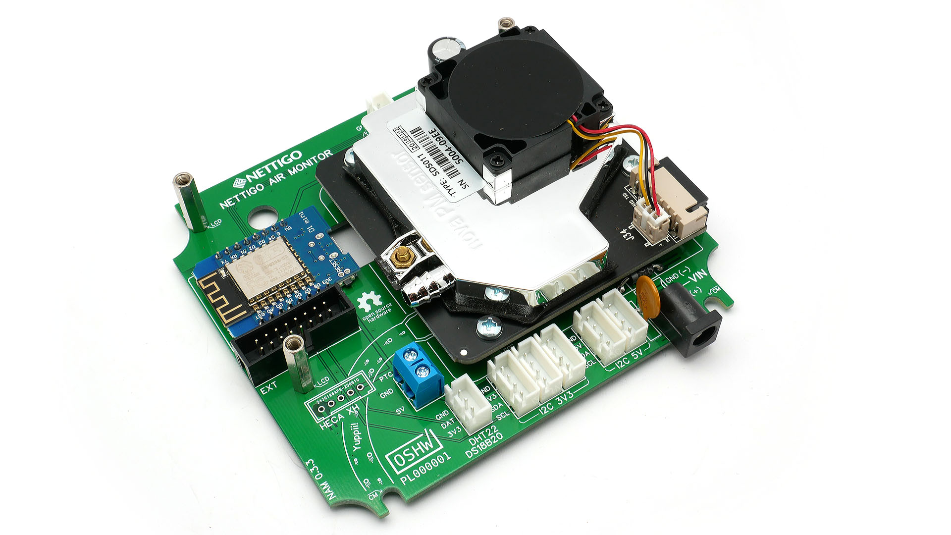
Using three long M3x8mm screws, screw the 18mm standoffs into the holes marked LCD. Tighten them really hard. The standoffs will allow in the future to mount various accessories without need for removing the motherboard from the enclosure. As you probably guessed, the standoffs are too short to mount the LCD screen directly on them. It is supposed to be a flexible system, so in the LCD set you will find appropriate F-M standoff extensions.
Do test before putting board into case.
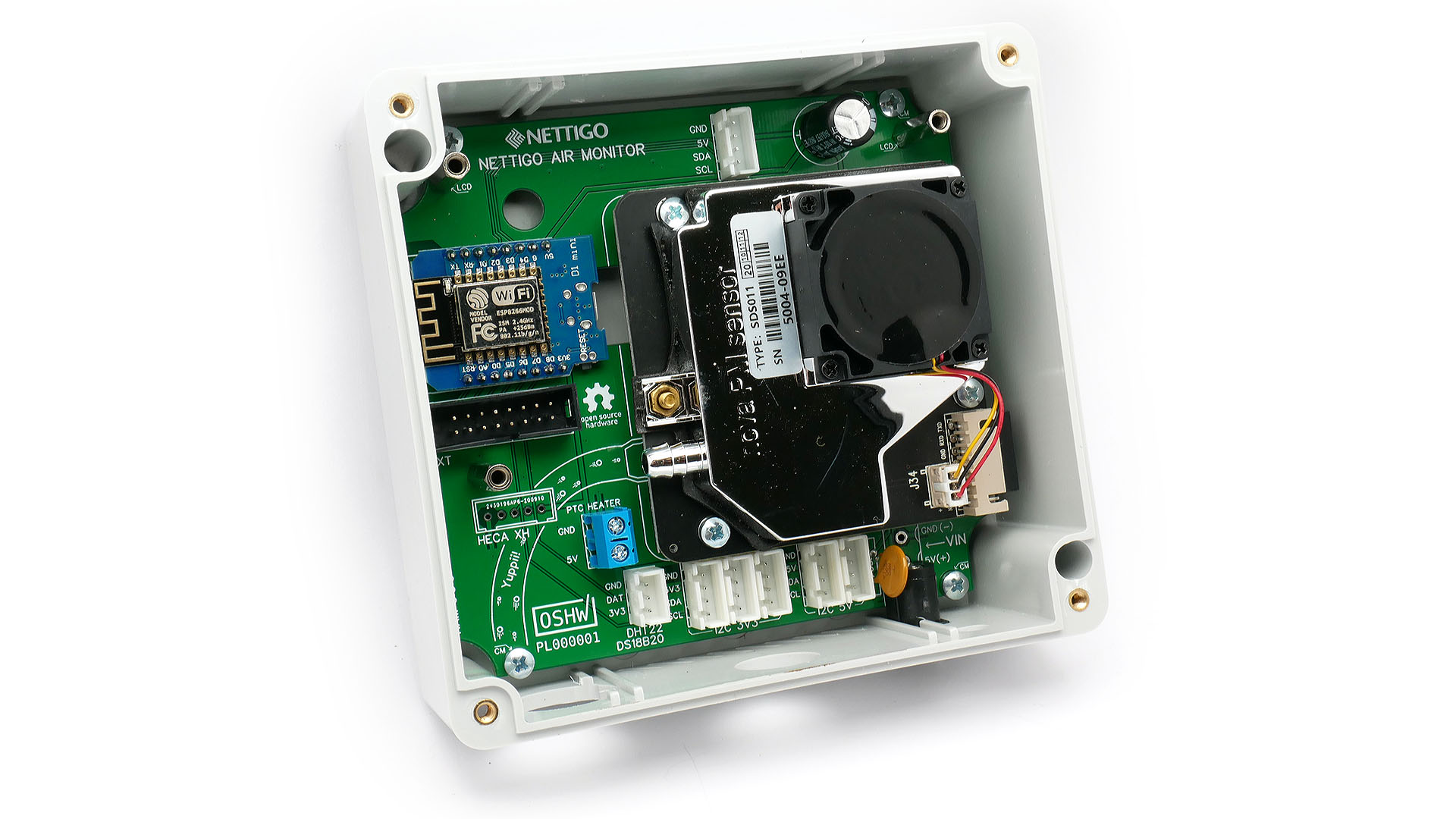
Check all solder joints again. Don't skip this step. We use a microscope for this, but any magnifying glass and proper light should work just as well. If everything looks fine, you can screw the motherboard to the enclosure.
Before mounting board inside of case place it on flat surface (make sure nothing will make shortcut) and connect power to board. You can start configuring firmware to make sure You have connectivity with board and SDS011 is working.
You will need four M3x5mm screws. Press firmly in the initial phase, and tighten carefully in the final phase. The screws need to thread the plastic so there is some resistance. Unfortunately, at the end of tightening, the resistance increases only slightly. This makes thread easy to twist. It would be better to use M3x6mm screws, but these are easily confused with the M3x5mm screws used for SDS011 standoffs. It is a compromise.
Congratulations! The motherboard is ready. You are not done with soldering, see next steps...