Document based on NAMF-2020-44, November 2022.
¶ First run
After the first power-up, startup may take anywhere from a few seconds to one minute (depending on whether the Wemos board had previously been powered on with NAMF installed). Subsequent boots should take only a few seconds, with connecting to WiFi taking most of the time.
This document is based on NAMF-2020-44. This version introduced an important interface change.
The most important difference is that since version -44 there is a default WiFi password in configuration mode. The password is nettigo.pl.
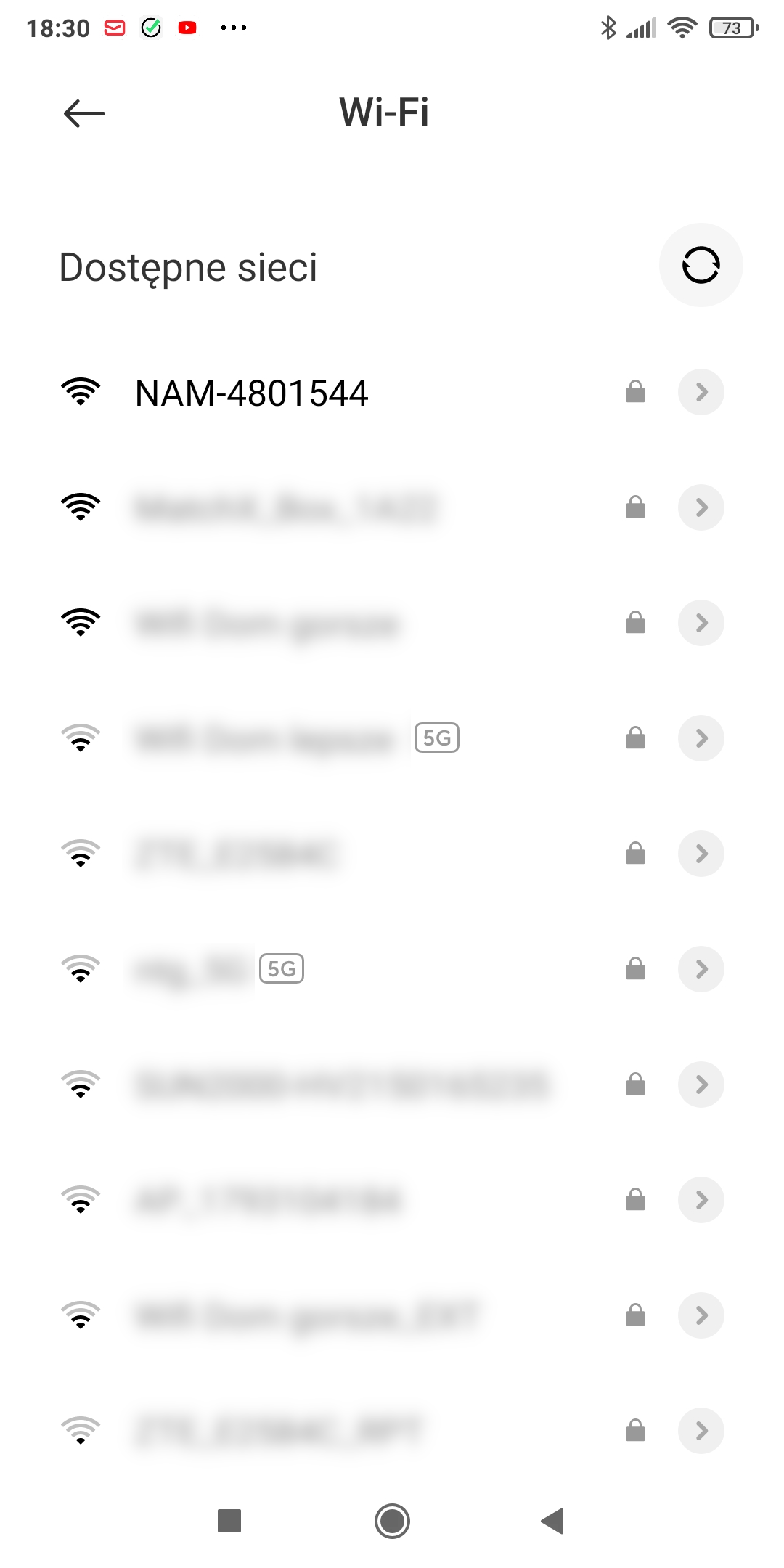
After the sensor boots, if this is the first run or if the sensor is used in a place where it cannot find the configured WiFi network, a configuration WiFi network will appear. It will be called "NAM-XXXXXXX", where XXXXXXX will be replaced by a number.
Write down that number; it will come in handy later. This number (also known as the sensor ID) should be printed on the bag with the Wemos board (in solder-it-yourself kits) or on a sticker on the mainboard (in presoldered devices).
Device configuration can be summarized as follows:
 Connect to the NAM-XXXXXXX WiFi network
- Provide the WiFi credentials for the sensor
- Restart
- Connect to the same WiFi network as the sensor and finish the configuration (the WiFi access point must not isolate devices on this network)
Version -44 introduced a new configuration interface, but a fragment of the old code remained. As a result, only a few basic parameters are saved during configuration through the access point (the WiFi network created by NAM). Therefore, you first need to configure WiFi, restart the device, and only then finish the configuration. This should be fixed in the next version.
After the restart (provided that NAM connects to the selected network), the NAM-XXXXXXX WiFi network will no longer be available. Your phone/computer should then be connected to the same WiFi network that was selected for NAM.
¶ Password!
Connect to this network. The default password is nettigo.pl. If your computer/phone has no other Internet connection apart from WiFi, the configuration page should open automatically. If that does not happen, open a web browser manually and enter 192.168.4.1 as the address.
You should see a green initial configuration panel. The first step is to configure WiFi access (yes, we are using a different sensor for this documentation than in the previous illustration, which is why the network/sensor names differ between the two screenshots).
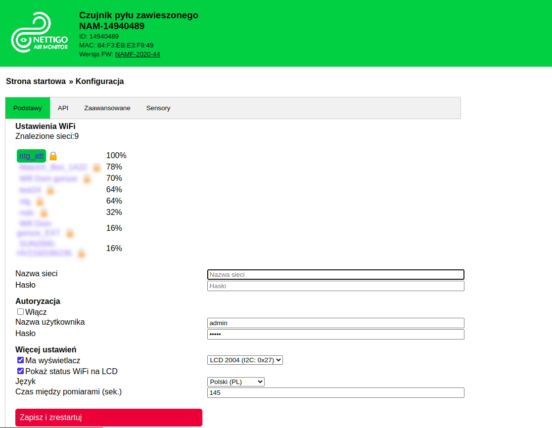
After a few seconds, a list of WiFi networks visible to the sensor should appear. Here we will connect to the ntg_att network, so click it.
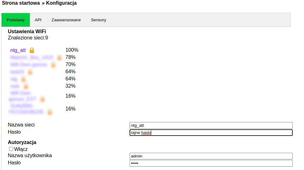
The network name will be copied to the appropriate field and the cursor will move to the password field. Now enter the password. As you can see in the screenshot, the password you type is visible. Why? Initially, the configuration network was not password-protected, so the password field was visible to emphasize that the transmitted data was not private. Since version -44, the network is encrypted, but there is still no "show entered password" option. To avoid typos, we have left the password visible for now (only at this stage; after the restart it will no longer be visible here).
Press "Save and restart". The sensor will reboot. If the WiFi password you entered was correct, the sensor will automatically connect to the Internet. Then, if the option is enabled, it will automatically download updates.
At the moment, we recommend configuring WiFi and Internet connectivity first. Leave the remaining configuration options until the sensor is connected to WiFi.
¶ How to find the sensor on the local network?
Enter http://nam-XXXXXXX.local/ in your browser, replacing XXXXXXX with the sensor ID. Did it work? Great — you can move on to the next section 
Didn't work? Keep reading.
First — perhaps you made a typo in the WiFi password? How can you check? Wait several dozen seconds after restarting NAM and see whether the NAM-XXXXXXX WiFi network is visible. If it is, NAM failed to connect to WiFi for some reason. The first "suspect" is an incorrectly entered password. Repeat the procedure of connecting to the NAM-XXXXXXX WiFi network and configure WiFi again.
If the NAM-XXXXXXX WiFi network is not present, that means one thing — NAM has connected to the selected WiFi network. Well, we can rule out the possibility that it is not powered on  . Since it is connected to the network, we now need to determine its IP address.
¶ If you have an LCD display
Users whose NAM is equipped with an LCD display have it easiest. Simply wait and watch the display. Within a few seconds, one of the screens will show the assigned IP address. Enter that address in your browser and you're done.
If your device does not have a display (or it has not been configured yet), you can find the sensor on the local network in at least two ways.
¶ Check the router administration panel
The first method requires access to your router. Log in to the router's administration panel and check the device list for anything new. Look for devices whose names begin with "ESP" or "NAM".
¶ Windows systems — Zeroconf / Apple Bonjour
The second method uses services such as Zeroconf / Apple Bonjour — sensors automatically announce their addresses on the network. If you have 64-bit Windows 10, entering the address shown at the beginning of this section should work. If it does not, install support for this protocol. Finding the sensor should then be relatively straightforward. To make sure you have the correct sensor ID, use the dns-sd -B command in the command prompt. It will list all devices advertising themselves on the network, including NAM sensors. If your sensor is on the list, entering http://nam-XXXXXXX.local/ in your web browser should take you directly to the administration panel. Of course, replace the Xs with your own ID from the initial configuration. If you want to find the sensor's IP address, simply use ping nam-XXXXXXX.local.
¶ Linux systems
On Linux systems, Zeroconf support is provided by the Avahi daemon. In most cases, it is installed by default in modern distributions. The link from the beginning of this section should work straight away. Just in case, avahi-browse -at should display a list of services advertised on the local network, and NAM should appear there. If it does, the link should definitely work. Of course, you must be connected to the same WiFi network as NAM.
¶ Android systems
Unfortunately, Android devices do not provide native support for this protocol, so you need to use third-party apps, such as the excellent PingTools Network Utilities or the much simpler Service Browser. You can use them to find the device and the sensor's IP address.
Once you know the IP address, enter it in your web browser and open the sensor page. It should look roughly like this:
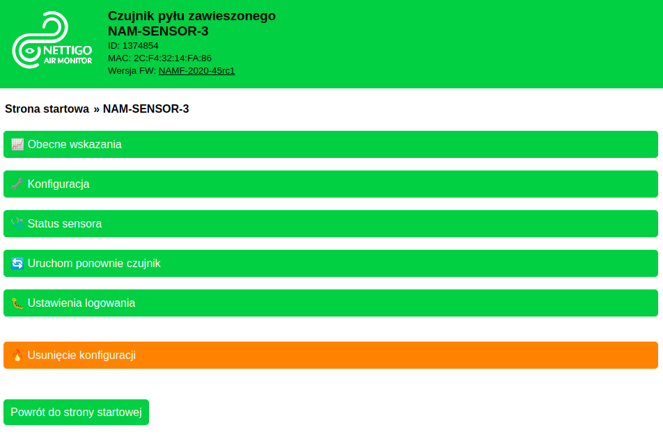
Success — we have access to the configuration!
¶ Further configuration (optional)
After selecting "Configuration" on the main screen, you will see the following page:
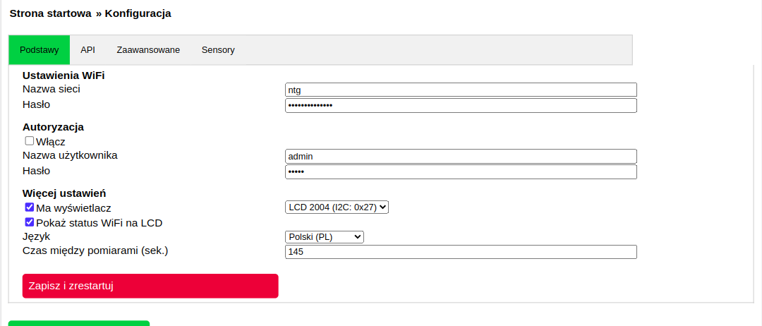
It is divided into tabs. We will go through them one by one. The first three tabs are saved together when you press Save and restart. This means you can make changes in all three tabs at the same time and then press any Save and restart button. Changes from all three tabs will be saved. The fourth tab works a little differently, but we will explain that in its section.
The first tab visible on the default screen is:
¶ Basics tab
Here we have gathered the settings that are used most often.
¶ WiFi settings
Here you can set the network name and password that the sensor will use to connect to the Internet. If you make a mistake and enter an incorrect password or network name, the sensor will enter initial configuration mode after restarting.
¶ Authentication
Here you can protect access to the sensor's web interface with a password. In NAMF, the default credentials are "admin" / "admin". Authentication is not enabled by default. It is good practice to enable it and change the default password. Do it now — if you leave it for later, you will probably never do it...
¶ More settings
If your NAM has a display, this is where you enable it. In addition to checking the Has display option, you need to select the correct display. The choice comes down to size and address. How do you know which one to select? Size — LCD Kit sets use a 20-character, 4-line display, so select 2004. And the address? It can be 0x27 or 0x3F. You can open the sensor's home page in a new window (Ctrl-click the NAM logo or the sensor name — both links lead to the home page) and go to the Sensor status page.
In the table shown there, somewhere near the beginning, you should see information about which device addresses are visible on the I2C bus (I2C/On the I2C bus). If a display is connected, either 27 or 3F should appear there. That is its address.
Show WiFi status on LCD — when enabled, one of the LCD screens displays information about the WiFi network the sensor is connected to: IP address, network name and signal strength.
Language — here you can change the NAMF interface language. This requires a restart and software reinstallation, so an Internet connection is necessary. To change the language, automatic updates must be enabled (Advanced tab).
Time between measurements — specifies how many seconds pass between data transmissions to external APIs. The default value of 145 seconds is inherited from Sensor Community and works well for standard applications. You can change this interval depending on your needs. A few notes if you want to do so:
- some APIs reject measurements sent too frequently (for example, intervals shorter than 60 seconds)
- with factory settings, the SDS011 operating mode (the default particulate matter sensor) requires an interval of at least 25–30 seconds; with shorter intervals it may not take measurements correctly
- reducing the transmission interval below 90 seconds may significantly shorten the life of the SDS011 — with a 90-second interval, the SDS011 laser diode has an estimated lifetime of about 2.5 years with standard settings
- some sensors take averaged measurements throughout the period between data transmissions, while others (such as the SDS011) take measurements shortly before the data is sent
¶ API tab
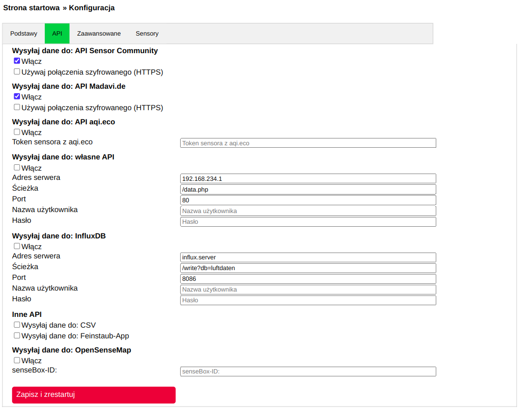
We describe in detail what can be done with sensor data, including how to configure the sensor for particular APIs, in a separate article. Here we provide only a brief overview.
The first two options enable or disable sending data to Sensor Community and madavi.de. For the Sensor Community API, you need to register your sensor there before it will appear on the map.
AQI.eco service has its own configuration. You can configure it as a custom API, as described in the service's control panel, but in NAMF you only need to paste the token here — the last part of the Path shown in the AQI.eco panel. This allows you to send data both to AQI.eco and to your own API.
Custom API — integration with any service capable of reading data sent by NAM. The data format is JSON. A file containing the most recently transmitted data can be viewed by opening the sensor's IP address with the /data.json path.
InfluxDB — a database for storing measurement data. NAMF currently supports protocol version 1. Here you can read, in English, how to set up InfluxDB with Grafana using Docker. This makes it easy to build your own service with data charts (for example, the previously mentioned Madavi uses Grafana to create charts).
¶ Advanced tab
This tab contains options that may be useful in less common situations.
Alternative WiFi network — here you can configure a second WiFi network. If the sensor cannot connect to the primary network configured in the Basics tab, it will try to connect to the network defined here.
Who might find this useful? People who maintain sensors that are later installed in other locations. You can configure your own "service" network here — if the sensor comes back to you for any reason, there is no need to change its configuration. It will connect to the second network, and when it returns to its permanent location it will still remember the login details for the primary network.
This is particularly useful in citizen sensor networks, where one person is usually responsible for technical maintenance.
Debug level — the default amount of diagnostic output. The range is 0 to 5. Zero means the fewest messages, 5 the most. The amount of diagnostic output can be changed on the /debug page (where the messages can also be viewed), but a level changed there does not survive a restart. Here you can set a value that is stored permanently.
- Level 0 — no messages
- Level 1 — errors only
- Level 2 — errors + warnings
- Level 3 — errors + warnings + minimal information
- Level 4 — errors + warnings + medium amount of information
- Level 5 — errors + warnings + maximum amount of information
Duration in router mode (sec.) — when NAM cannot connect to any WiFi network after a restart, it starts its own access point, just like during the initial configuration. This parameter specifies how many seconds that AP remains visible (10 minutes by default).
Transmit power 0–20.5 (dBm) — the transmit power of the WiFi chipset. By default, it is set to the maximum permitted value.
WiFi mode (1=B / 2=G / 3=N) — selects which variant of the WiFi protocol is used by the sensor.
Network name — when NAM starts its own access point, the default WiFi network name is NAM-XXXXXXXX. Here you can set your own name. This name is also advertised through Zeroconf, so if you set it to, for example, NAM-SENSOR, it will be available on the local network at http://nam-sensor.local/
Password — the password used for the WiFi network in configuration mode. If left blank, the default nettigo.pl password will be used. The password must contain at least 8 characters.
Update firmware automatically — probably self-explanatory  . Leave it enabled. It must be enabled if you want to change the interface language. For everyone, we recommend leaving the Stable channel selected as the update source. The beta channel is intended for users who want to preview upcoming changes.
OLED SSD1306 — specifies whether the system includes a graphical OLED display based on the SSD1306 controller. For example: https://nettigo.pl/products/wyswietlacz-oled-0-96-i2c-128x64-ssd1306-niebieski We do not recommend it for general use because it is very small and the text is difficult to read, but... perhaps someone needs one?
RGB LED bar — an experimental display in the form of an LED indicator showing air quality. It is not yet available for sale.
Send diagnostic data to Nettigo — just as the name suggests, when this option is enabled, diagnostic data is sent to our system at every startup and periodically every several hours. This includes information such as configured sensors, memory usage/status, number of errors, etc. Each sensor receives a UUID when it connects to our service for the first time. That UUID is later used to identify the sensor. A new UUID is assigned when switching between the beta/stable update channels or after deleting the configuration.
¶ Sensors tab
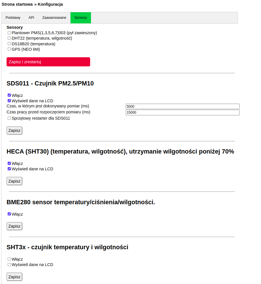
In this section you can enable support for individual sensors. This tab works a little differently, as mentioned earlier. The sensors listed at the beginning of the page, down to the familiar red Save and restart button, form one configuration section together with the three previous tabs. All changes made in those first three tabs and in the fourth tab above the button are saved together.
Sensors configured using the forms below the red button are each saved separately. Because the entire page reloads, these sensors must be configured one by one: make changes to one sensor, save them, then move on to the next.
Configuration changes for sensors in this second section do not restart the entire NAM and are applied on the fly, at least for basic settings. Advanced options may require a restart, but if so, this will be stated next to the relevant option.
The general rule is: do not enable a sensor in the configuration if that sensor is not physically present in the system. Enabling such a "missing" sensor may cause side effects such as interface delays, restarts, etc.
- Plantower PMS(1,3,5,6,7)003 (particulate matter) — support for Plantower PMS5001, PMS1003, PMS5003, PMS6003 and PMS7003 sensors. It is connected instead of the SDS011. By default, leave it disabled.
- GPS (NEO 6M) — support for GPS using the tinyGPS standard. It allows sensor coordinates to be sent together with the data packet and can also serve as a time source. It connects through the EXT socket, using pins D5 and D6.
- Sensors connected to the DHT22 socket (physically, only one sensor type can be connected):
- DHT22 (temperature, humidity) — the basic temperature and humidity sensor used in the luftdaten.info project. We decided to use more accurate Bosch sensors instead. Supports AM2302, AM2320 and similar devices. Connect it to the DHT22 socket on the NAM board.
- DS18B20 (temperature) — a temperature sensor from Dallas. This sensor requires an additional 4.7 kOhm pull-up resistor between the DAT and 3V3 pins.
This is where the list of "old" sensors ends. Below you will find the configuration for sensors/systems using the new NAMF software subsystem, which is why they are configured a little differently.
All "old" sensors collect data shortly before a measurement is sent; usually this is a single measurement. PMSx003 works in the same way as the SDS011 described below.
Each sensor in the new subsystem has an Enable option and, if it has data that can be displayed, a Show data on LCD option. Enabling the latter adds screens with data from that sensor to the list of screens shown on the LCD.
¶ SDS011 (particulate matter) — the primary sensor measuring airborne particulate matter
This is currently the sensor most commonly used in the Sensor Community network. It has one drawback: the relatively short lifetime of its laser diode. When operating continuously, the manufacturer guarantees correct operation for about 11 months. To extend this period, interval-based operation is used. PM concentration is measured for a short time (from a few to several seconds), and those few measurements are averaged.
The next two configuration options control these parameters. The first specifies how long the actual measurement lasts. The SDS sends data once per second; the measurements are averaged and the resulting value is sent to the API. The second specifies how long the SDS should run before the measurement begins, allowing outside air to be drawn in and fill the measurement chamber.
¶ HECA
This module does not have any special configuration. New options will probably appear in the next version (beta NAMF-2020-45rc1 already has them). These are humidity thresholds at which the HECA heater is activated. This allows you to control the humidity range of the air supplied to the SDS011. This is an advanced setting; the default configuration is perfectly sufficient.
Data from HECA is sent to the API, but because the module includes a heater, keep in mind that these charts are mainly useful for checking that the heater is operating and doing its job, rather than for determining actual temperature/humidity.
¶ BME280
Temperature, pressure and humidity measurements are taken 5 times during each measurement interval, and averaged values are sent to the API.
¶ SHT3x
HECA uses an SHT30. If you want, you can add a second SHT31 sensor to NAM. It must use I2C address 0x45, because 0x44 is already occupied by HECA. The SHT31 is more accurate than the BME280, but it does not provide pressure measurements.
Measurements are taken every 15 seconds and the averaged results are sent to the API.
¶ BMP180/280
These sensors are predecessors of the BME280. They do not measure humidity, only temperature and pressure. Together with the SHT31, they were used as a replacement for the BME280 during a period when BME280 sensors were unavailable on the market.
The Sensor inside enclosure option should be used when the BMP sensor is installed inside the NAM enclosure. In that case, temperature data (which is artificially increased by heat from HECA and the ESP) is not sent to the API. Some APIs (Sensor Community) may then fail to display BMP readings correctly on the map when temperature data is missing.
¶ SPS30
The SPS30 particulate matter sensor can be used instead of the SDS011. Advantages: long diode lifetime (continuous operation and measurements are possible), measurement of PM1 and PM4 as well, and particle count data in addition to an approximate mass conversion. Drawbacks? The connection to HECA has not yet been solved (the SPS30 lacks the convenient air inlet found on the SDS011), and mounting it inside the NAM enclosure is also an issue because it has no mounting holes.
¶ Network Watchdog
After you provide the specified IP address, NAM will periodically use a ping to check connectivity. If there is no connection for 3 consecutive API data transmission cycles, the watchdog will restart NAM.
Note: if you enter an unreachable IP address here, NAM will keep restarting periodically...
¶ Winsen MHZ14A — CO2 sensor
The MHZ14A was an inexpensive CO2 sensor (it is no longer available). Its accuracy in the range of atmospheric CO2 concentrations was not particularly high, but it was the only sensor that could be implemented easily. The good news is that a new sensor from Winsen should be available soon. It is software-compatible and offers a slightly better measurement range (not artificially limited to 400 ppm at the lower end) as well as slightly better accuracy, so it should be possible to use it with NAM.