The following instructions apply to the Nettigo Air Monitor in version 0.3.3 STD. If you have a different version, see the Knowledge Base section for instructions. The general principle of soldering and assembly is common to all our sensors - but keep in mind that they differ in details.
I assume the NAM motherboard and HECA are already soldered. So we will not repeat ourselves. You are probably already familiar with the list of the necessary tools, health and safety precautions and soldering methods. If not please take a look at our guide.
¶ Soldering
This kit can be soldered in two ways. The first is to use two separate cables and solder both sensors individually. The second way is to use one cable and solder both sensors like a sandwich. In this tutorial, we will focus on the "sandwich" method.
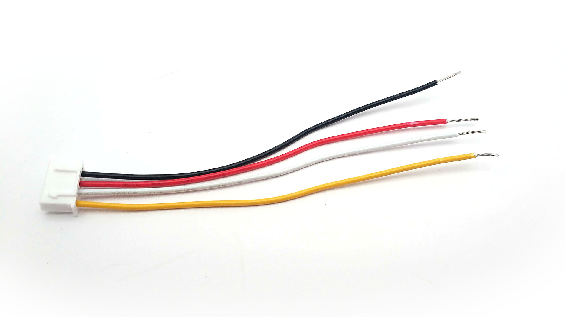
Sensors to NAM 0.3 are connected with cables with XH2.54 plug. They have 4 wires. Black and red are responsible for delivering power. White and yellow are the signals of the I²C bus. At each stage of soldering, it is worth paying attention to whether the wires are soldered in the right places.
- Red wire -
3V3sometimes marked asVccorVin - Black wire -
GND - Yellow wire -
SCL - White wire -
SDA
First, strip some more insulation from the wires. About 10mm of exposed cable will be sufficient. This is more than You would remove for standard soldering. You have to leave enough wire to allow solder second board to wires.
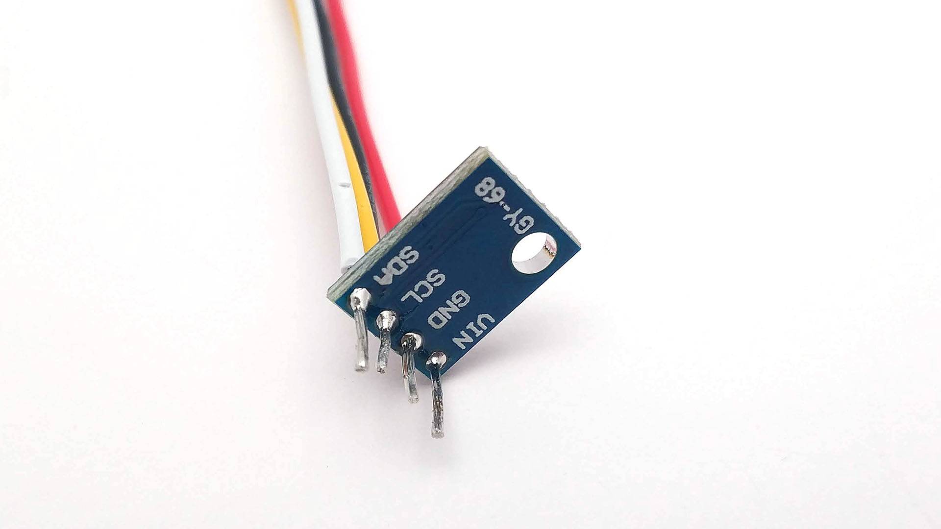
We put long cables through the holes of the BMP180 module. Pay attention to the correct order. If it's correct, solder the cables using a little tin with rosin.
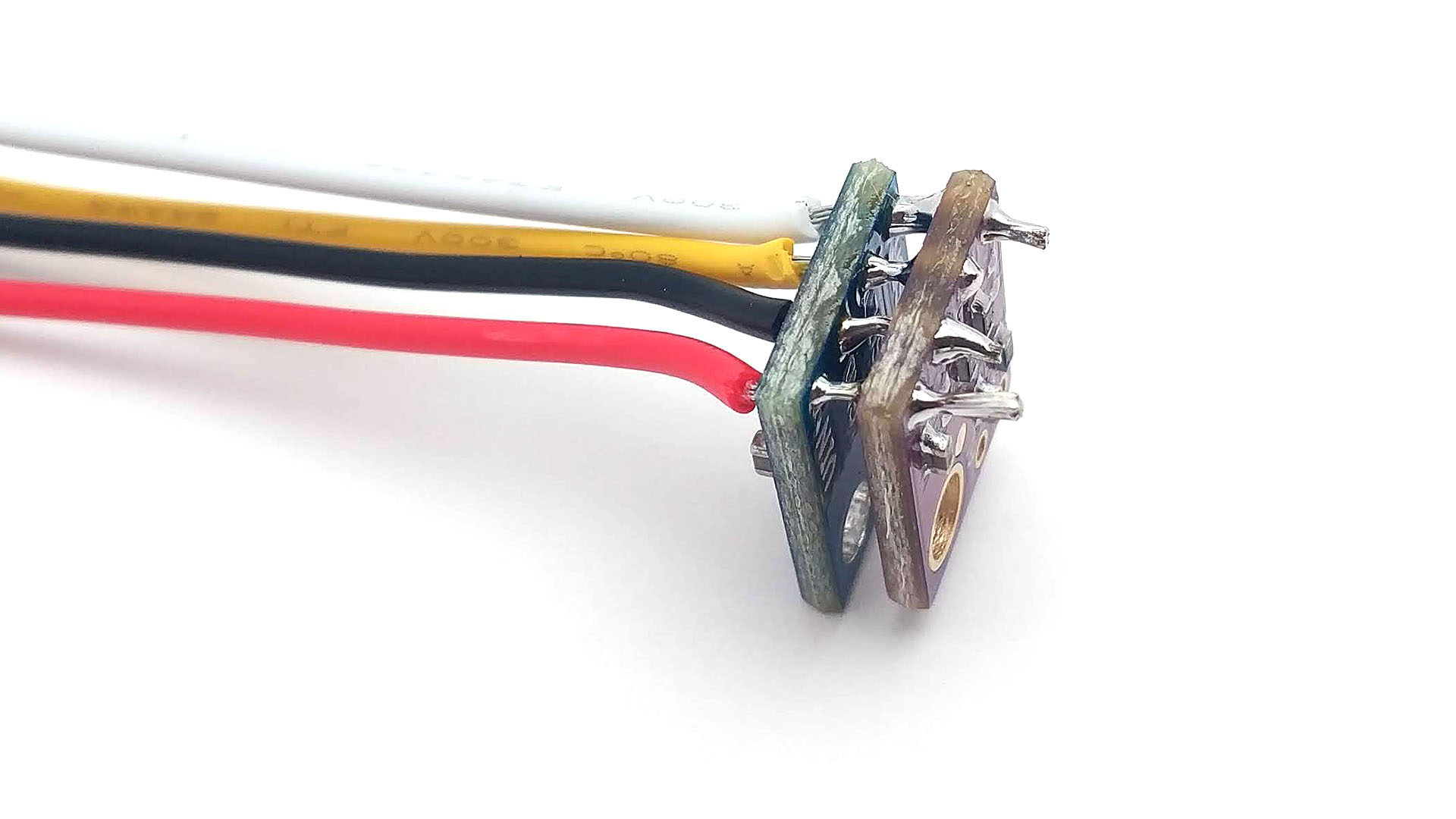
Put the SHT31 module on the sticking out ends of the cable. Pay attention to the order of cables. The large mounting holes in the modules should align. There should be some free space between the modules. Then solder the module.
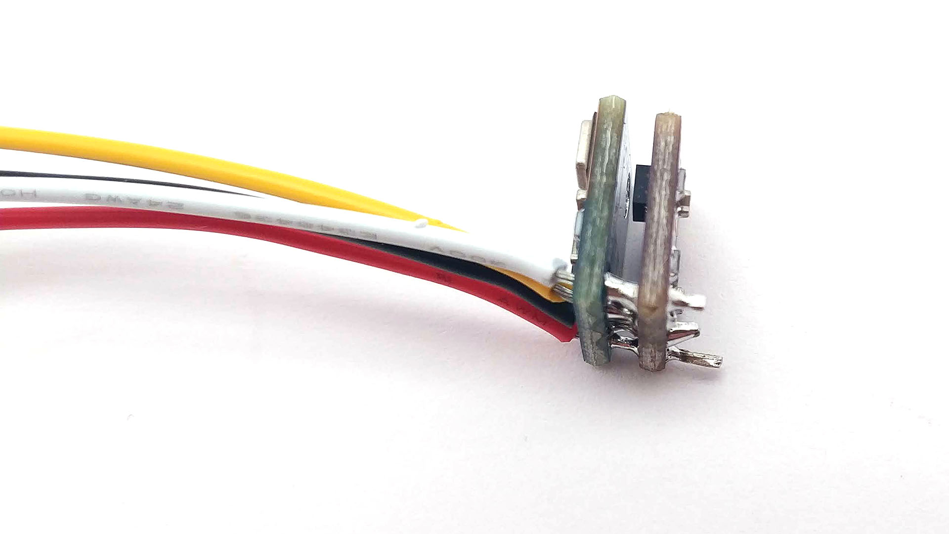
The black square body of the SHT31 sensor should be placed between the module PCB's as shown in the picture above. Make sure there is some space above the black sensor housing so that air can freely reach it.
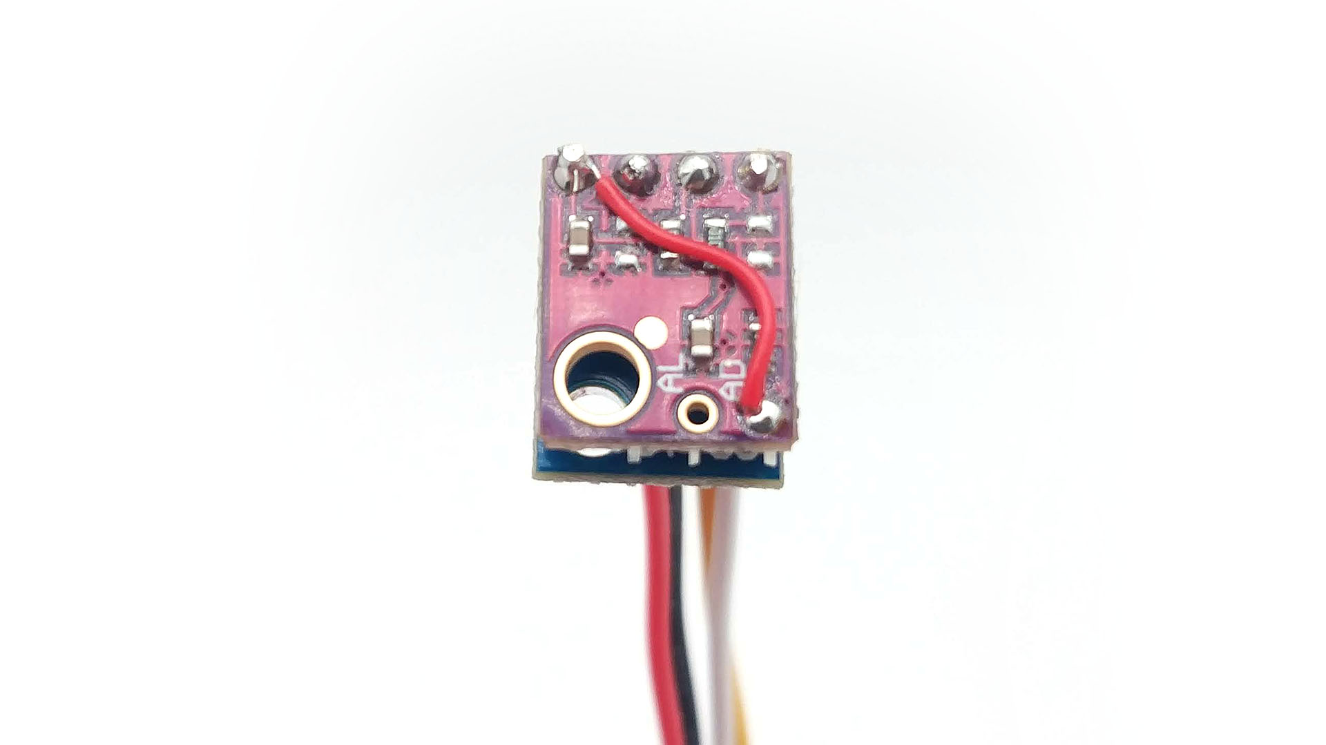
In the next step we need to connect the pad described as AD with the 3V3 (Vcc / Vin) power pin to which the red cable is connected. For this we use a thin, short cable.
To remove insulation from endings of this thin cable You can use solder iron - just heat up ends of wire and it will melt insulation.
¶ Placing in case
Do test Your SHT31/BMP180 module before placing in case!
Before placing SHT31/BMP180 in case test if Your module is working. Use NAM motheboard and connect SHT31/BMP180 to 3.3V I2C socket. Power up NAM (remeber to place board in safe place, where nothing can shortcut joints on lower side of PCB) and log in (I assume You have NAMF already configured when soldering motherboard. If not see config). If there is no reading wait until measurement count will show 1 at least.
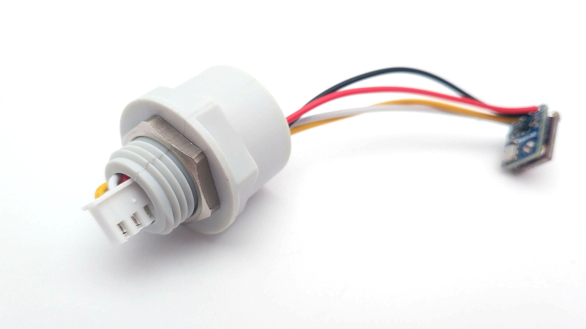
The white XH2.54-4P plug should be put through the hole in the housing. At first glance, it may seem impossible. But the plug goes sideways without any problems, as shown in the picture.
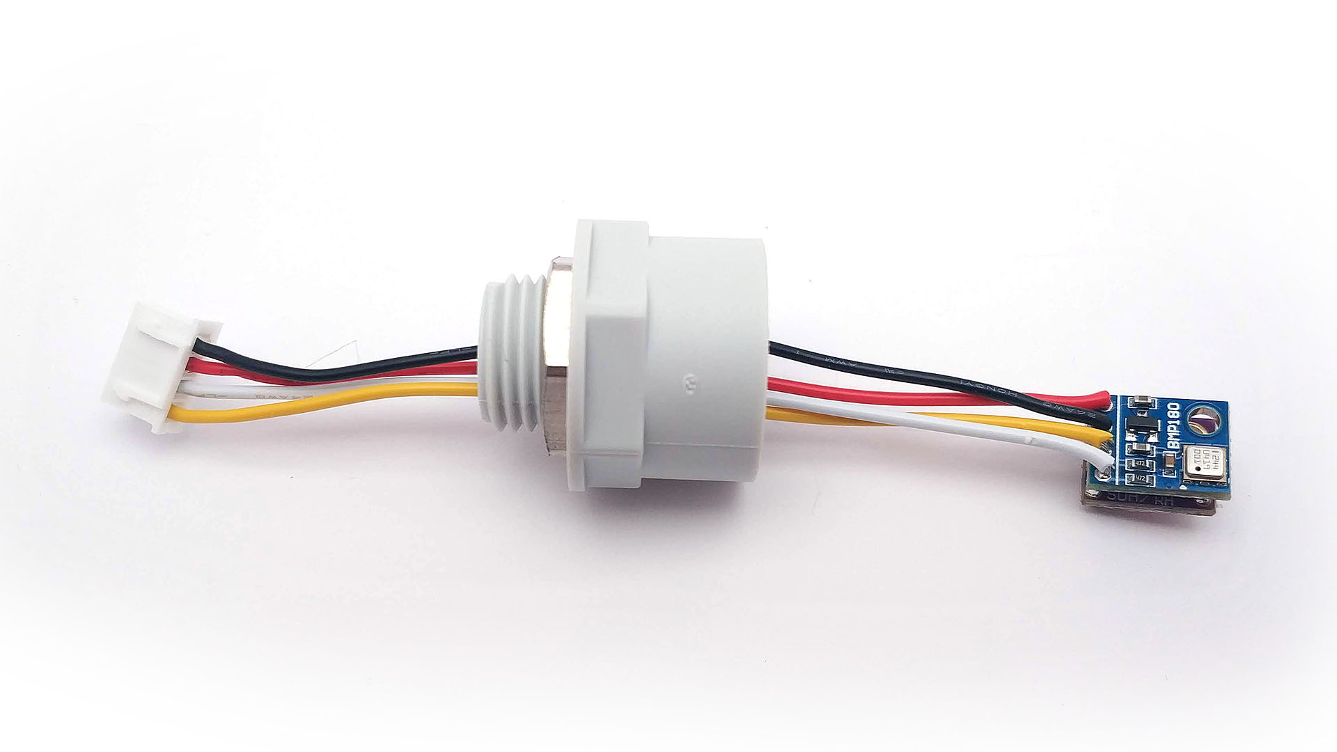
The cables at the module should be bent as shown in the photo. Of course, be careful not to short-circuit them.
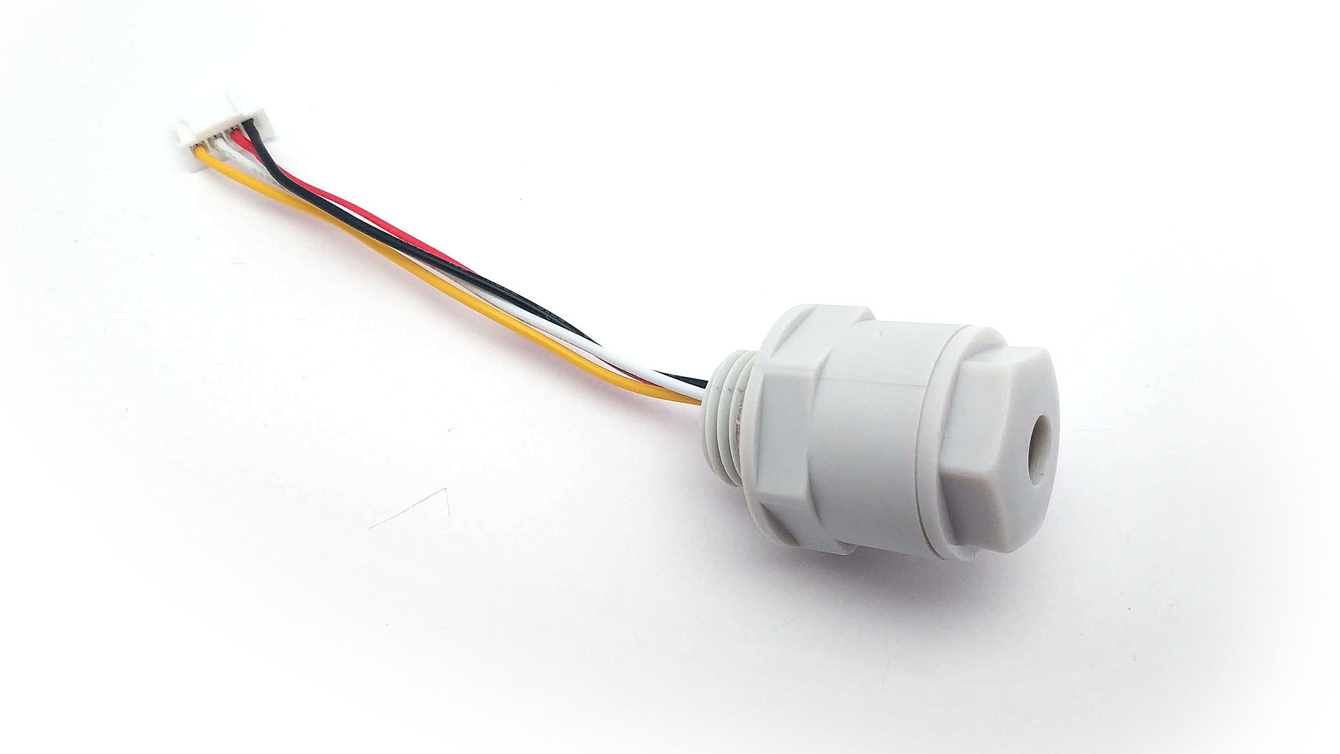
Place the sensor board inside the housing. Then screw on the plug with the hole.
The module is already in the housing, but on the back we have a large gap through which the warm air from the inside of the NAM sensor can heat the sensor. It's a good idea to fill the gap.
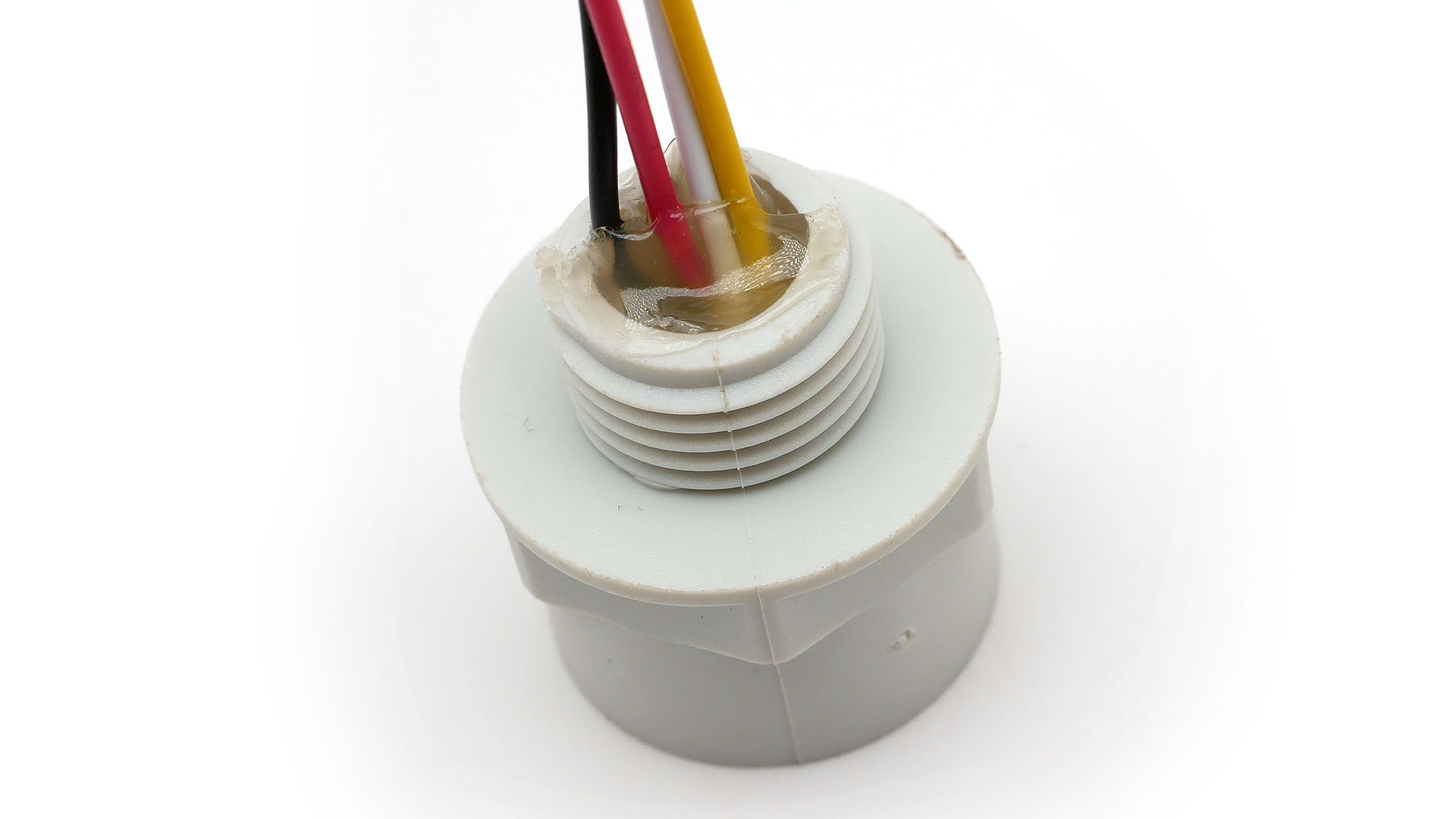
A hot glue is perfect for this. If you don't have hot glue, you may use silicone, epoxy or a piece of foam - although for foam we recommend using one that does not absorb water.
¶ Next step
- NAM 0.3.3 STD final assembly
- NAM 0.3.3 PRO final assembly - not ready yet