As for November 2022 kit sold by us is for NAM in version 0.3.3. If You have earlier version, check this older instruction (only in Polish).
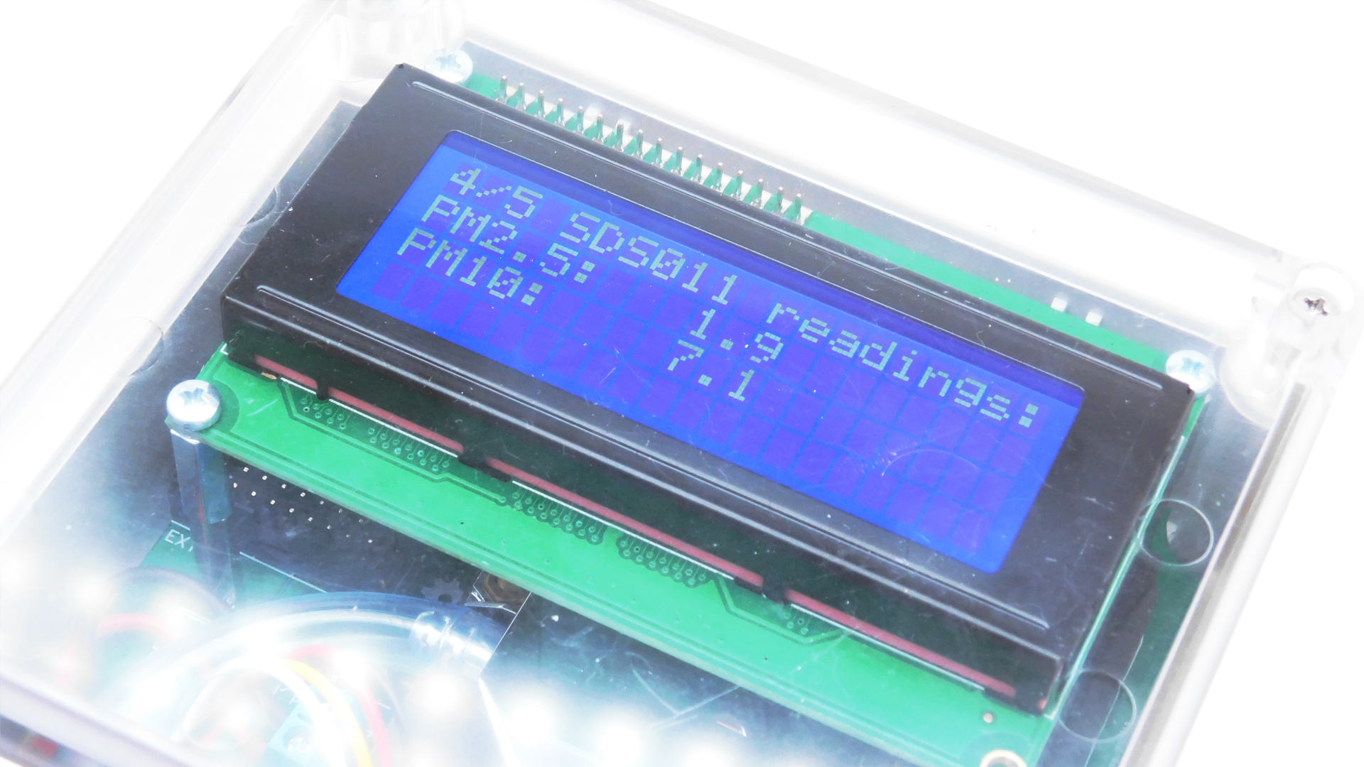
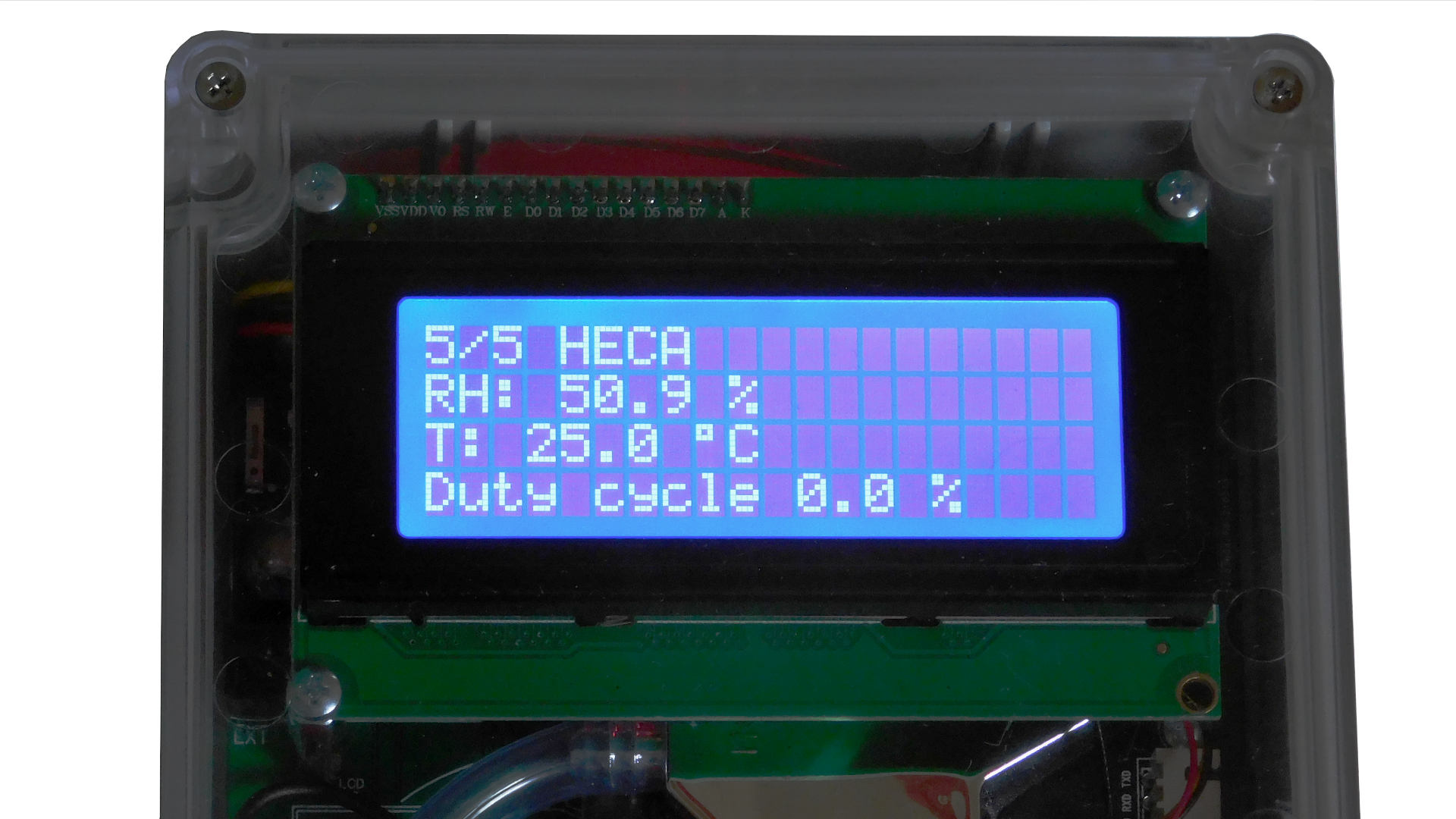
LCD kit for NAM will dispaly sensor readings dirrectly on LCD. Display is placed directly under clear cover, so it can be installed in outdoor sensor (but avoid direct sunlight on LCD).
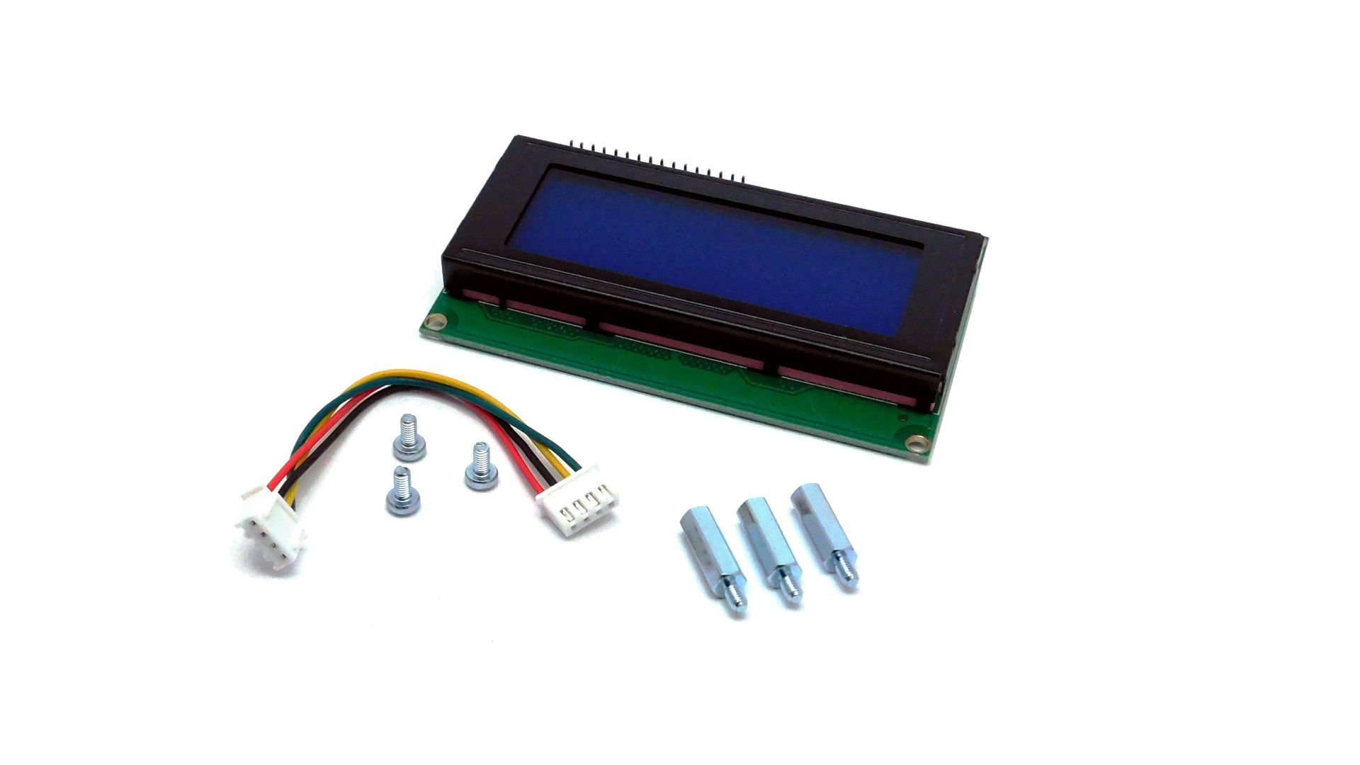
Kit consists from character LCD (20x4) with I2C intreface, connecting cable, spacers and screws.
¶ Assembly and connecting
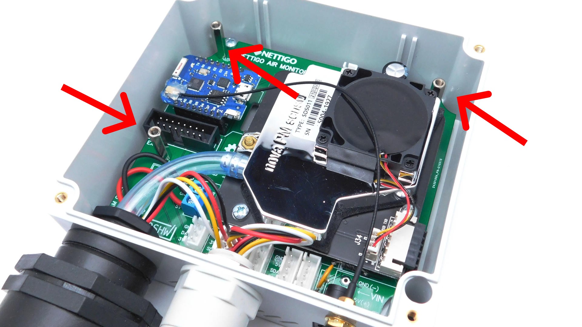
After cover removal You have access to three spacers on NAM PCB. Screw in 3 spacers from LCD kit. Now spacers are high enough to place LCD PCB over SDS011.
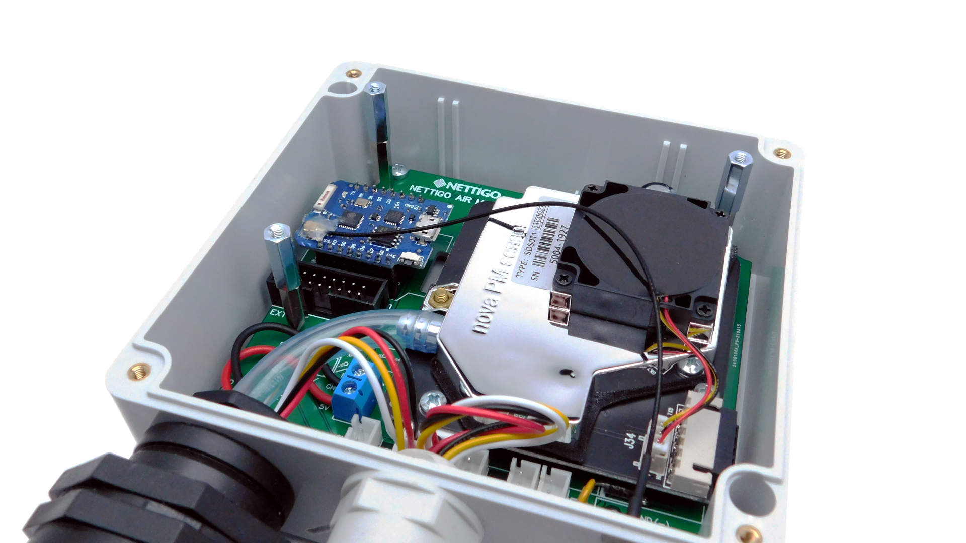
Sometimes spacers are from different vendors, and ther is slight difference in size. Well, I'd like have only such problems in life...
Double check polarity in next step!
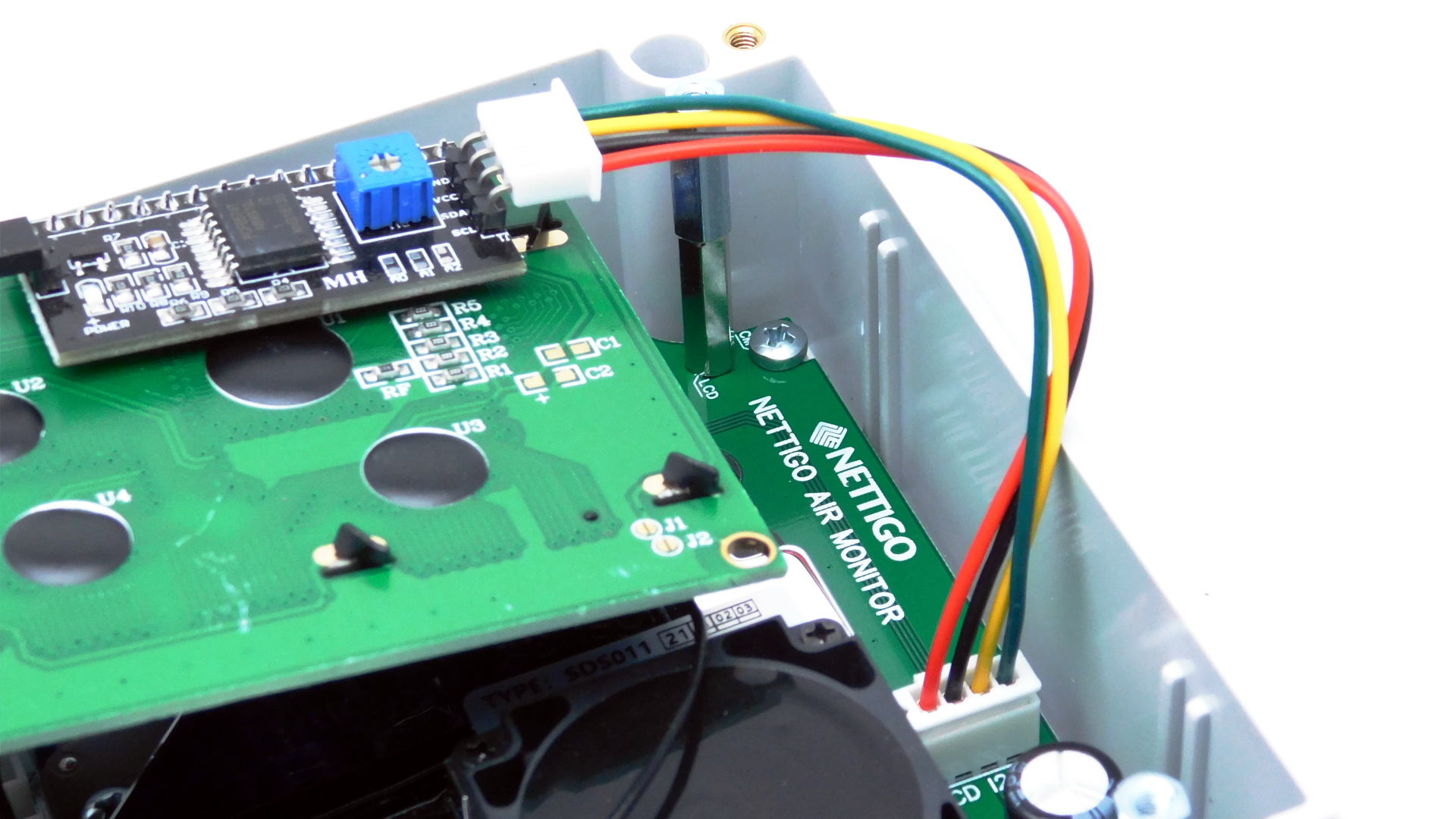
Connecting cable has XH connetor and is co called cross cable. So DONT PAY ATTENION TO WIRE COLORS ON PICTURE, ORDERIG OF COLORS DEPENDS ON WHICH END YOU CONNECT OT MAINBOARD Proceed as follows:
- Connect cable to I2C LCD socket on NAM mainboard. There is only way how You can connect cable to socket.
- Check whch wire color corresponds for GND (first connector from NAM PCB edge).
- Place second connector onto I2C pins on LCD. Double check that wire with GND matches GND on LCD!
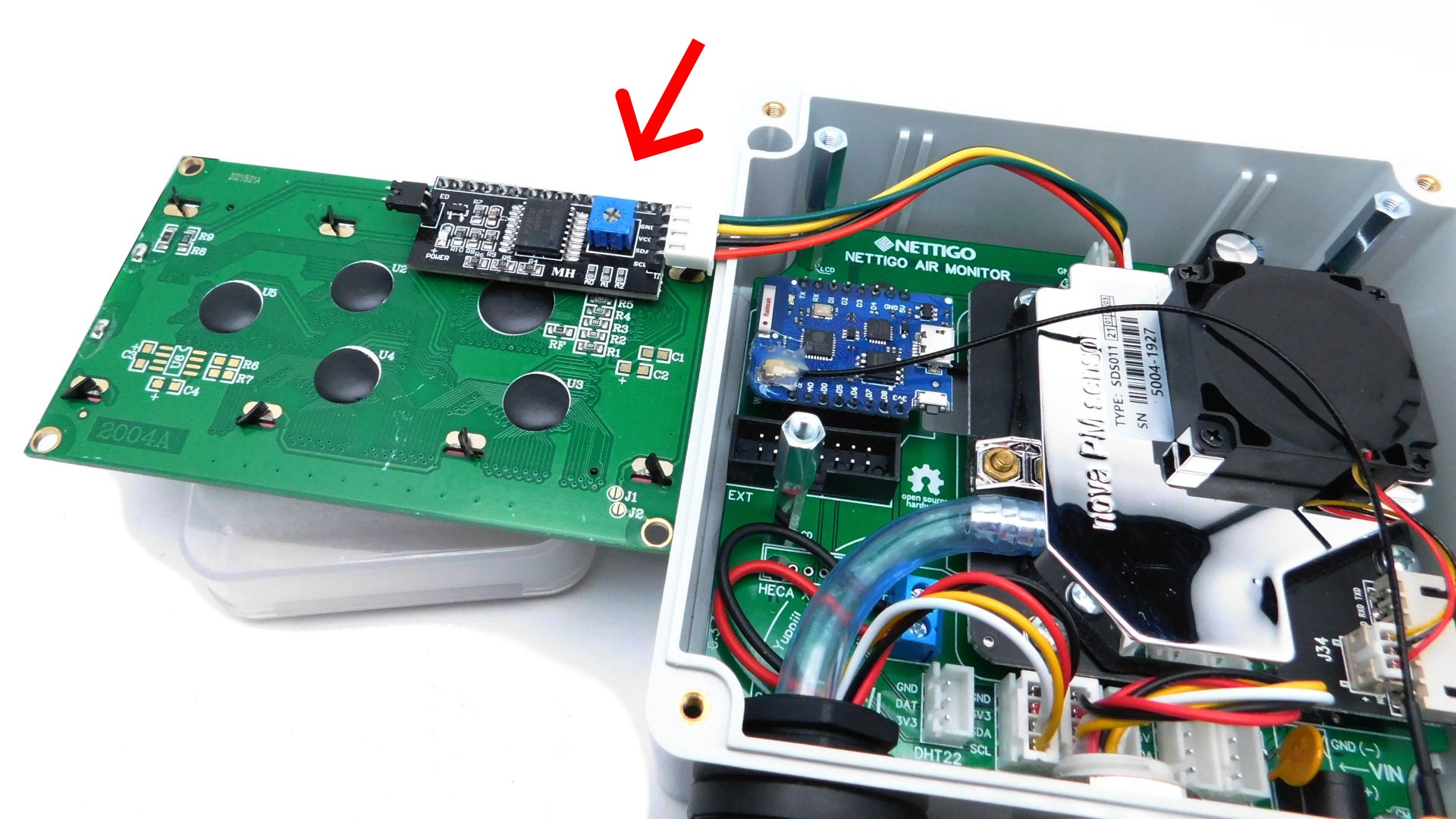
Before You put LCD on spacers and screw it You have to adjust contrast potentiometer. After You screw LCD to spacers there will be no access to potentiometer (blue box, marked with arrow on picture). Place LCD next to NAM, power on NAM (have You double checked if I2C cable is connected correctly? If not, before You plug power to NAM is time to do it).

Vistit /status page on sensor. One of first entry there is list of devices seen on I2C bus. LCD will have address 0x27 or 0x3F. Check which one is present, and then navigate to /config page and select proper option next to LCD settings.
Save config. After sensor will boot take small screw driver and gently turn potentiometer on back of LCD until You get clear and readable text on display. Now You are ready to screw LCD on spacers.
Turn power of, before You try to mount LCD. Screws can fall inside NAM case. If NAM will be powered You may damege ESP8266 when screw make shortcircut.
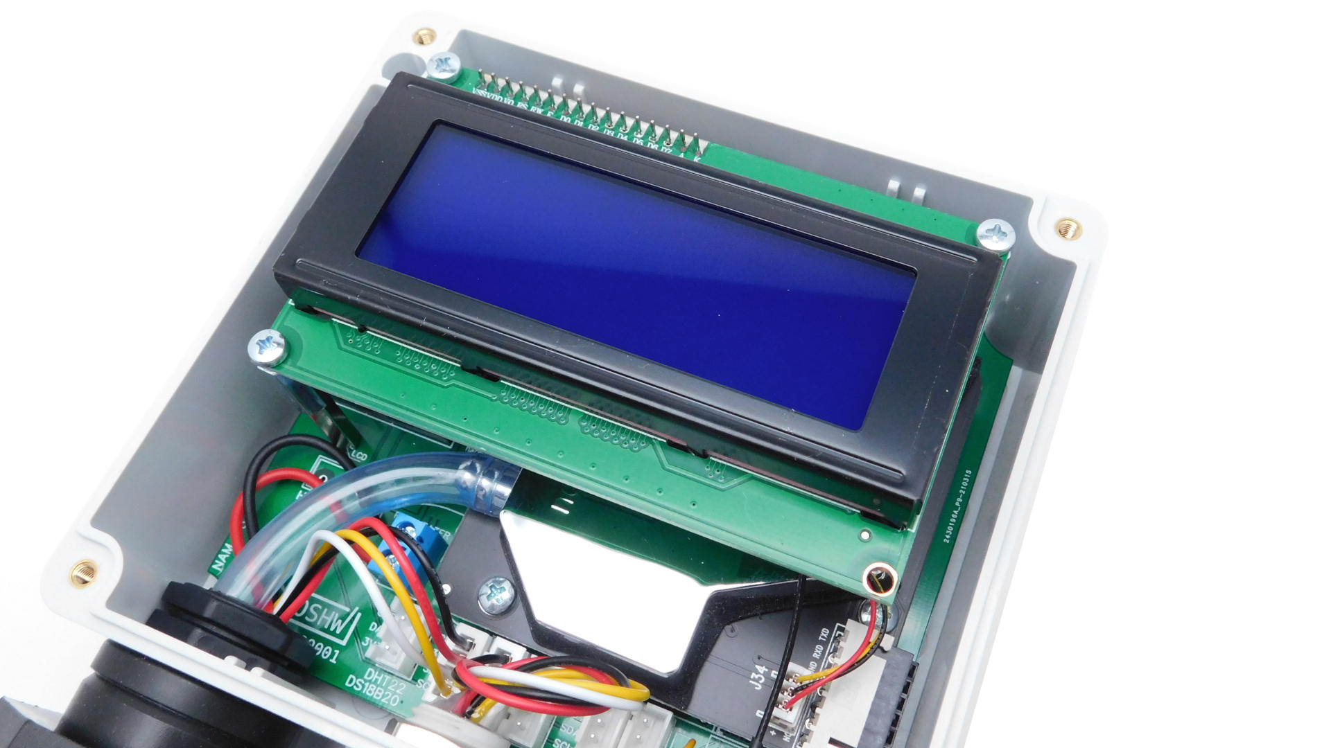
Put LCD on spacers, screw it and You can place cover back on NAM. Device is ready!
